Practical hints
Flat tire
▼ Flat tire
Warning!
The dimensions of the Minispare wheel are different from those of the road wheels. As a result, the vehicle handling characteristics change when driving with a Minispare wheel mounted. Adapt your driving style accordingly.
The Minispare wheel is for temporary use only. When driving with Minispare wheel mounted, ensure proper tire inflation pressure and do not exceed a vehicle speed of 50 mph (80 km/h).
Drive to the nearest Mercedes-Benz Center as soon as possible to have the Minispare wheel replaced with a regular road wheel.
Never operate the vehicle with more than one Minispare wheel mounted.
Preparing the vehicle
▶ Park the vehicle as far as possible from moving traffic on a hard surface.
▶ Turn on the hazard warning flasher (▷ page 123).
▶ Turn the steering wheel so that the front wheels are in a straight ahead position.
▶ Set the parking brake (▷ page 54).
▶ Move the gear selector lever to P (manual transmission: to first or reverse gear).
▶ Turn off the engine (▷ page 56).
▶ Remove the SmartKey from the starter switch.
▶ Have any passenger exit the vehicle at a safe distance from the roadway.
Open doors only when conditions are safe to do so.
Mounting the Minispare wheel
Preparing the vehicle
Prepare the vehicle as described (▷ page 399).
▶ Take the wheel wrench, the wheel bolts, and the jack out of the trunk (▷ page 377).
▶ Take the Minispare wheel out of the trunk (▷ page 380).
399
Practical hints
Flat tire
Lifting the vehicle
- Prevent the vehicle from rolling away by blocking wheels with wheel chocks or other sizable objects.
One wheel chock is included with the vehicle tool kit (> page 377).
When changing wheel on a level surface:
- Place the wheel chock in front of and another sizable object behind the wheel that is diagonally opposite to the wheel being changed.
When changing wheel on a hill:
- Place the wheel chock and another sizable object on the downhill side blocking both wheels of the other axle.
Warning!
The jack is designed exclusively for jacking up the vehicle at the jack take-up brackets built into both sides of the vehicle. To help avoid personal injury, use the jack only to lift the vehicle during a wheel change. Never get beneath the vehicle while it is supported by the jack. Keep hands and feet away from the area under the lifted vehicle. Always firmly set parking brake and block wheels before raising vehicle with jack.
Do not disengage parking brake while the vehicle is raised. Be certain that the jack is always vertical (plumb line) when in use, especially on hills. Always try to use the jack on level surface. Make sure the jack arm is fully seated in the jack take-up bracket. Always lower the vehicle onto sufficient capacity jackstands before working under the vehicle.
P40.10-3340-31
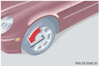
- On wheel to be changed, loosen but do not yet remove the wheel bolts (approximately one full turn with wrench).
400
Practical hints
Flat tire
The jack take-up brackets are located directly behind the front wheel housings and in front of the rear wheel housings.
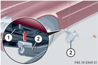
① Take-up bracket ② Jack
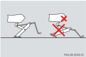
► Place jack ② on firm ground. ► Position jack ② under take-up bracket ① so that it is always vertical (plumb-line) as seen from the side, even if the vehicle is parked on an incline.
P40.00-2040-31
► Jack up the vehicle until the wheel is a maximum of 1.2 in (3 cm) from the ground. Never start engine while vehicle is raised.
Warning!
The jack is intended only for lifting the vehicle briefly for wheel changes. It is not suited for performing maintenance work under the vehicle.
• Never start the engine when the vehicle is raised. • Never lie down under the raised vehicle.
Removing the wheel
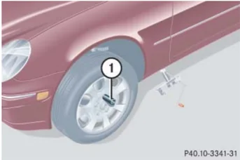
P40.10-3341-31
① Alignment bolt
► Unscrew upper-most wheel bolt and remove. ► Replace this wheel bolt with alignment bolt ① supplied in the tool kit. ► Remove the remaining bolts.
! Do not place wheel bolts in sand or dirt. This could result in damage to the bolts and wheel hub threads.
► Remove the wheel.
401
Practical hints
Flat tire
Mounting the spare wheel
 P40.10-3165-31
① Wheel bolt for light alloy rims ② Wheel bolt for Minispare wheel or other steel rims (located in trunk with spare wheel)
! Wheel bolts ② must be used when mounting the Minispare wheel or other steel rims. The use of any wheel bolts other than wheel bolts ② for the Minispare wheel or other steel rims will physically damage the vehicle's brakes.
► Clean contact surfaces of wheel and wheel hub.
! To avoid paint damage, place wheel flat against hub and hold it there while installing first wheel bolt.
Warning!
Always replace wheel bolts that are damaged or rusted.
Never apply oil or grease to wheel bolts. Damaged wheel hub threads should be repaired immediately. Do not continue to drive under these circumstances! Contact an authorized Mercedes-Benz Center or call Roadside Assistance.
Incorrect wheel bolts or improperly tightened wheel bolts can cause the wheel to come off. This could cause an accident. Make sure to use the correct wheel bolts.
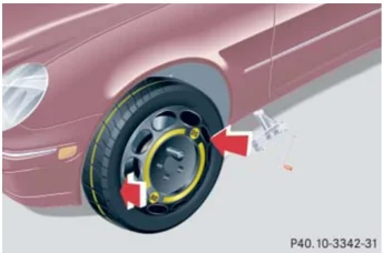
 P40.10-3342-31
► Guide spare wheel onto the alignment bolt and push it on.
► Insert wheel bolts and tighten them slightly.
402
Practical hints
Flat tire
 P40.10-3343-31
► Unscrew the alignment bolt, install last wheel bolt and tighten slightly.
Warning!
Only use genuine equipment Mercedes-Benz wheel bolts. Other wheel bolts may come loose.
Do not tighten the wheel bolts when the vehicle is raised. Otherwise the vehicle could fall off the jack.
Lowering the vehicle
► Lower vehicle by turning crank counterclockwise until vehicle is resting fully on its own weight.
► Remove the jack.
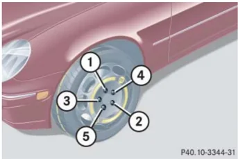
 P40.10-3344-31
① - ⑤ Wheel bolts
► Tighten the five wheel bolts evenly, following the diagonal sequence illustrated (① to ), until all bolts are tight. Observe a tightening torque of 80 lb-ft (110 Nm).
Warning!
Have the tightening torque checked after changing a wheel. The wheels could come loose if they are not tightened to a torque of 80 lb-ft (110 Nm).
Before storing the jack, it should be fully collapsed, with handle folded in (storage position) (▷ page 379).
► Store the jack and the other vehicle tools in the trunk.
403
Practical hints
Battery
The battery is located in the engine compartment on the right hand side.
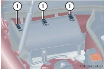
① Clamps
Removing filter box: ► Release clamps ①. ► Remove filter box.
Installing filter box: ► Insert filter box properly. ► Secure it with clamps ①.
Warning!
Failure to follow these instructions can result in severe injury or death.
Observe all safety instructions and precautions when handling automotive batteries (▷ page 302).
Never lean over batteries while connecting, you might get injured.
Battery fluid contains sulfuric acid. Do not allow this fluid to come in contact with eyes, skin or clothing. In case it does, immediately flush affected area with water and seek medical help if necessary.
A battery will also produce hydrogen gas, which is flammable and explosive. Keep flames or sparks away from battery, avoid improper connection of jumper cables, smoking, etc.
❗ Never loosen or detach battery terminal clamps while the engine is running or the SmartKey is in the starter switch. Otherwise the alternator and other electronic components could be severely damaged.
Have the battery checked regularly by an authorized Mercedes-Benz Center.
Refer to Maintenance Booklet for maintenance intervals or contact an authorized Mercedes-Benz Center for further information.
Warning!
Do not place metal objects on the battery as this could result in a short circuit.
Use leak-proof battery only to avoid the risk of acid burns in the event of an accident.
404
Practical hints
Battery
Warning! With a disconnected battery
- you will no longer be able to turn the SmartKey in the starter switch
- the gear selector lever will remain locked in position P
 ① Negative terminal
② Positive terminal cover
Disconnecting the battery
- Turn off the engine (▷ page 56).
- Turn off all electrical consumers.
- Remove SmartKey from starter switch.
- Open the hood (▷ page 296).
- Remove the filter box (▷ page 404).
- Disconnect the battery negative lead from negative terminal ①.
- Remove cover ② from the positive terminal.
- Disconnect the battery positive lead.
Removing the battery
- Remove the screw-nuts securing the battery.
- Remove the battery bracket.
- Take out the battery.
Charging and reinstalling the battery
- Charge battery in accordance with the instructions of the battery charger manufacturer.
- Reinstall the charged battery. Follow the previously described steps in reverse order.
Warning! Never charge a battery while still installed in the vehicle. Gases may escape during charging and cause explosions that may result in paint damage, corrosion or personal injury.
405
Practical hints
Battery
Reconnecting the battery
- Turn off all electrical consumers.
- Remove SmartKey from starter switch.
- Connect the battery positive lead and fasten its cover ②.
- Connect the battery negative lead.
NEVER invert the terminal connections!
- Reinstall the filter box (▷ page 404).
The battery, its filler caps and the vent tube must always be securely installed when the vehicle is in operation.
The following procedures must be carried out following any interruption of battery power (e.g. due to reconnection):
- Set the clock (▷ page 145). Vehicles with COMAND*: See COMAND operator's manual.
- Synchronize side windows (▷ page 244).
- Synchronize tilt/sliding sunroof* (▷ page 248).
Batteries contain materials that can harm the environment if disposed of improperly. Large 12 volt storage batteries contain lead. Recycling of batteries is the preferred method of disposal. Many states require sellers of batteries to accept old batteries for recycling.
406
Practical hints
Jump starting
▼ Jump starting
Warning!
Failure to follow these directions will cause damage to the electronic components, and can lead to a battery explosion and severe injury or death.
Never lean over batteries while connecting or jump starting, you might get injured.
Battery fluid contains sulfuric acid. Do not allow this fluid to come in contact with eyes, skin or clothing. In case it does, immediately flush affected area with water, and seek medical help if necessary.
A battery will also produce hydrogen gas, which is flammable and very explosive. Keep flames or sparks away from battery, avoid improper connection of jumper cables, smoking, etc.
Attempting to jump start a frozen battery can result in it exploding, causing personal injury.
Read all instructions before proceeding.
If the battery is discharged, the engine can be started with jumper cables and the battery of another vehicle. Observe the following:
- Jump starting should only be performed when the engine and catalytic converter are cold.
- Do not start the engine if the battery is frozen. Let the battery thaw out first.
- Only jump start from batteries with the same voltage rating (12 V). Jump starting with a more powerful battery could damage the vehicle's electrical system, which will not be covered by the Mercedes-Benz Limited Warranty.
- Only use jumper cables with sufficient cross-section and insulated terminal clamps.
- Always make sure the jumper cables are not on or near pulleys, fans, or other parts that move when an engine is started or running.
! Avoid repeated and lengthy starting attempts.
Do not attempt to start the engine using a battery quick charge unit.
If engine does not run after several unsuccessful starting attempts, have it checked at the nearest authorized Mercedes-Benz Center.
Excessive unburned fuel generated by repeated failed starting attempts may damage the catalytic converter and may present a fire risk.
Make sure the jumper cables do not have loose or missing insulation.
Make sure the cable clamps do not touch any other metal part while the other end is still attached to a battery.
407
Practical hints
Jump starting
Warning! Keep flames or sparks away from battery. Do not smoke.
Observe all safety instructions and precautions when handling automotive batteries (▷ page 302).
The battery is located in the engine compartment on the right hand side. The terminals for jump starting are located in front of the battery.
▶ Make sure the two vehicles do not touch.
▶ Turn off all electrical consumers.
▶ Apply parking brake.
▶ Shift gear selector lever to position P (manual transmission: to Neutral).
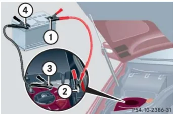
① Positive terminal of charged battery ② Positive under hood terminal in front of discharged battery ③ Negative under hood terminal in front of discharged battery ④ Negative terminal of charged battery
▶ Connect positive terminal ① of the charged battery with positive under hood terminal ② in front of the discharged battery with the jumper cables. Clamp cable to charged battery ① first.
▶ Start engine of the vehicle with the charged battery and run at idle speed.
▶ Connect negative terminal ④ of the charged battery with negative under hood terminal ③ in front of the discharged battery with the jumper cables. Clamp cable to charged battery ④ first.
▶ Start the engine of the disabled vehicle.
You can now again turn on the electrical consumers. Do not turn on the lights under any circumstances.
▶ Remove the jumper cables first from negative terminals ③ and ④ and then from positive terminals ② and ①.
You can now turn on the lights.
▶ Have the battery checked at the nearest authorized Mercedes-Benz Center.
! Vehicles with automatic transmission and/or 4MATIC: Do not tow-start the vehicle.
408
Practical hints
Towing the vehicle
▼ Towing the vehicle
Mercedes-Benz recommends that the vehicle be transported with all wheels off the ground using flatbed or appropriate wheel lift/dolly equipment. This method is preferable to other types of towing.
! Use flatbed or wheel lift/dolly equipment with the SmartKey in the starter switch turned to position 0.
Do not tow with sling-type equipment. Towing with sling-type equipment over bumpy roads will damage radiator and supports.
To prevent damage during transport, do not tie down vehicle by its chassis or suspension parts.
Switch off the tow-away alarm* (▷ page 91) and deactivate the automatic central locking (▷ page 153).
When circumstances do not permit the recommended towing methods, the vehicle may be towed with all wheels on the ground or front wheels raised (except vehicles with 4MATIC) only so far as necessary to have the vehicle moved to a safe location where the recommended towing methods can be employed.
! Vehicles with automatic transmission and/or 4MATIC: Do not tow-start the vehicle.
! Vehicles with 4MATIC: Do not tow with one axle raised. Doing so could damage the transfer case, which is not covered by the Mercedes-Benz Limited Warranty.
All wheels must be on or off the ground. Observe instructions for towing the vehicle with all wheels on the ground.
! If the vehicle is towed with the front axle raised (not permissible for vehicles with 4MATIC), the engine must be shut off (SmartKey in starter switch position 0 or 1). Otherwise the ESP will immediately be engaged and will apply the rear wheel brakes.
When towing the vehicle with all wheels on the ground, the gear selector lever must be in position N (manual transmission: gears disengaged) and the SmartKey must be in starter switch position 2.
When towing the vehicle with all wheels on the ground or the front axle raised, the vehicle may be towed only for distances up to 30 miles (50 km) and at a speed not to exceed 30 mph (50 km/h).
409
Practical hints
Towing the vehicle
! To be certain to avoid a possibility of damage to the drivetrain, however, we recommend the drive shaft be disconnected at the rear axle drive flange (vehicles with 4MATIC: disconnected at the front and rear axle drive flanges) for any towing beyond a short tow to a nearby garage.
Warning! If circumstances require towing the vehicle with all wheels on the ground, always tow with a tow bar if:
- the engine will not run
- there is a malfunction in the power supply or in the vehicle's electrical system
as that will be necessary to adequately control the towed vehicle.
Prior to towing the vehicle with all wheels on the ground, make sure the SmartKey is in starter switch position 2.
If the SmartKey is left in starter switch position 0 for an extended period of time, it can no longer be turned in the switch. In this case, the steering is locked. To unlock, remove SmartKey from starter switch and reinsert.
i To signal turns while being towed with the hazard warning flasher in use, switch on ignition and activate the combination switch for the left or right turn signal in the usual manner – only the selected turn signal will operate.
Upon canceling the turn signal, the hazard warning flasher will operate again.
410
Practical hints
Towing the vehicle
Warning!
With the engine not running, there is no power assistance for the brake and steering systems. In this case, it is important to keep in mind that a considerably higher degree of effort is necessary to brake and steer the vehicle. Adapt your driving accordingly.
! When towing the vehicle with all wheels on the ground, please note the following:
With the automatic central locking activated and the SmartKey in starter switch position 2, the vehicle doors lock if the left front wheel as well as the right rear wheel are turning at vehicle speeds of approx. 9 mph (15 km/h) or more.
Switch off the tow-away alarm* (▷ page 91).
To prevent the vehicle doors from locking, deactivate the automatic central locking (▷ page 153).
Towing of the vehicle should only be done using the properly installed towing eye bolt. Never attach tow cable, tow rope or tow rod to vehicle chassis, frame or suspension parts.
i If the battery is disconnected or discharged
- the SmartKey will not turn in the starter switch. For more information, see “Battery” (▷ page 404) and “Jump starting” (▷ page 407).
- the gear selector lever will remain locked in position P. For information on manually unlocking the transmission gear selector lever see (▷ page 386).
411
Practical hints
Towing the vehicle
Installing towing eye bolt
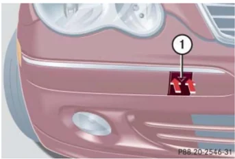
① Cover on right side of front bumper.
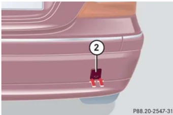
② Cover on right side of rear bumper.
Removing cover
- Press mark on cover ① or ② in direction of arrows.
- Lift cover off to reveal threaded hole for towing eye bolt.
The towing eye bolt is supplied with the tool kit (located in the compartment underneath the trunk floor).
- Screw towing eye bolt in to its stop and tighten with lug wrench.
Reinstalling cover
- Fit cover ① or and snap into place.
412
Practical hints
Fuses
▼ Fuses
The electrical fuses in your vehicle serve to stop the supply of electricity to a device that is malfunctioning. This helps to prevent damage to the other vehicle electronics.
The following aids are available to help you change fuses (▷ page 413):
- Fuse chart
- Spare fuses
- Fuse extractor
Warning! Only use fuses approved for Mercedes-Benz with the specified amperage for the system in question. Otherwise, a short circuit could result and cause a fire.
! Only install fuses that have been tested and approved by Mercedes-Benz and that have the specified amperage rating.
Otherwise, electrical parts or systems could be damaged.
Never attempt to repair or bridge a blown fuse. Have the cause determined and remedied by an authorized Mercedes-Benz Center.
The electrical fuses are located in different fuse boxes:
- Main fuse box in passenger compartment (▷ page 414)
- Fuse box in engine compartment (▷ page 414)
- Fuse box in trunk (▷ page 416)
Aids for changing fuses
Fuse chart The fuse chart is found in the main fuse box in the passenger compartment (▷ page 414). The amperages of the fuses are also given there.
Spare fuses Spare fuses are found in the vehicle tool kit in the spare wheel well (▷ page 377).
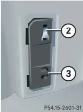
Fuse extractor The fuse extractor is found in the fuse box cover in the trunk (▷ page 416).
413
Practical hints
Fuses
Main fuse box in passenger compartment
The main fuse box is located in the passenger compartment on the driver’s side of the cockpit.
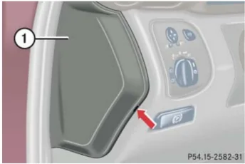
① Main fuse box cover
Opening fuse box
▶ Open the driver’s door.
▶ Pull fuse box cover ① open with a screw driver or similar tool (see arrow).
▶ Remove fuse box cover ① rearward.
Closing fuse box
▶ Attach fuse box cover ① in the front.
▶ Fold fuse box cover ① in until it engages.
Fuse box in engine compartment
The fuse box is located in the engine compartment on the driver’s side.
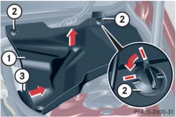
① Cover Screws ③ Retainer
414
Practical hints
Fuses
Removing cover
- Twist screws ② 90° counterclockwise.
- Lift the rear of cover ①.
- Slide out retainer ③ and remove cover ① by pulling towards front.
Opening fuse box
 ④ Fuse box cover
⑤ Clamps
- With a dry cloth, remove any moisture from the fuse box.
- Release clamps ⑤.
- Remove fuse box cover ④.
Closing fuse box
- Make sure that the sealing rubber is properly positioned.
- Press fuse box cover ④ down and secure with clamps ⑤.
Installing cover
- Insert cover ① sideways into retainer ③.
- Twist screws ② 90° clockwise.
415
Practical hints
Fuses
Fuse box in trunk
The fuse box is located in the trunk behind the left-hand trim panel.
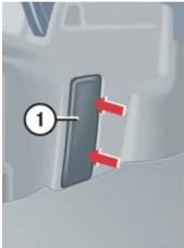
P54.15-2601-31
① Trim panel ② Fuse extractor ③ Fuse box cover
Opening fuse box
▶ Pull away trim panel ①. ▶ Remove fuse box cover ③.
Closing fuse box
▶ Insert fuse box cover ③ until it engages. ▶ Insert trim panel ①.
416