Climate Controls
MANUAL HEATING AND AIR CONDITIONING SYSTEM
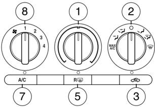
- Temperature selection: Controls the temperature of the airflow in the vehicle.
- Mode selections: Controls the location of the airflow in the vehicle. See the following for a brief description of each selection.
MAX A/C: Distributes recirculated air through the instrument panel vents to cool the vehicle. This re-cooling of the interior air is more economical and efficient. Recirculated air may also help reduce undesirable odors from entering the vehicle.
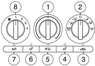
: Distributes air through the instrument panel vents.
: Distributes air through the instrument panel vents and the floor vents.
O (OFF): Outside air is shut out and the climate system is turned off.
: Distributes air through the floor vents.
: Distributes air through the windshield defroster vents and floor vents.
: Distributes air through the windshield defroster vents. Can be used to clear the windshield of fog and thin ice.
- Recirculation control : Press to activate/deactivate air recirculation in cabin. Recirculated air may reduce the amount of time to cool down the interior of the vehicle and may also help reduce undesired exterior odors from reaching the interior of the vehicle. Recirculation engages automatically with selection of MAX A/C or can be engaged manually in any other mode selection except (defrost). Recirculation may turn off automatically in all airflow selections except MAX A/C.
35
Climate Controls
- Passenger heated seat: Press to activate or deactivate the passenger side heated seat. Note: The passenger heated seat will turn off automatically after 10 minutes of use.
- Rear defroster (R ): Press to activate/deactivate the rear window defroster. Refer to Rear window defroster later in this section for more information.
- Driver heated seat: Press to activate or deactive on the driver side heated seat. Note: The driver heated seat will turn off automatically after 10 minutes of use.
- A/C: Press to activate/deactivate air conditioning. Use with recirculated air to improve cooling performance. Engages automatically in MAX A/C, (defrost) and (floor/defrost).
- Fan speed adjustment: Controls the volume of air circulated in the vehicle.
Operating tips
- To reduce fog build up on the windshield during humid weather, place the air flow selector in the (defrost) position.
- To reduce humidity build up inside the vehicle, do not drive with the airflow selector in the O (OFF) position or with recirculated air engaged.
- Do not put objects under the front seats that will interfere with the airflow to the back seats.
- Remove any snow, ice or leaves from the air intake area at the base of the windshield.
- To improve the A/C cool down, drive with the windows slightly open for 2-3 minutes after start up or until the vehicle has been "aired out."
For maximum cooling performance in MAX A/C mode:
- Move temperature control to the coolest setting.
- Set the fan to the highest speed initially, then adjust to maintain comfort.
36
Climate Controls
For maximum cooling performance in panel or panel/floor modes:
- Move temperature control to the coolest setting.
- Select A/C and recirculated air ( ) to provide colder airflow.
- Set the fan to the highest speed initially, then adjust to maintain comfort.
To aid in side window defogging/demisting in cold weather:
- Select .
- Select A/C.
- Adjust the temperature control to maintain comfort.
- Set the fan speed to the highest setting.
- Direct the outer instrument panel vents towards the side windows.
- To increase airflow to the outer instrument panel vents, close the vents located in the middle of the instrument panel.
Do not place objects on top of the instrument panel as these objects may become projectiles in a collision or sudden stop.
REAR WINDOW DEFROSTER (R ) Ensure that the ignition is in the 3 (ON) position. Press the control to clear the rear window of thin ice and fog. The LED will illuminate.
The rear window defroster turns off automatically after 15 minutes, or when the ignition is turned to the 1 (OFF/LOCK) position. To manually turn off the defroster before 15 minutes have passed, push the control again.
Do not use razor blades or other sharp objects to clean the inside of the rear window or to remove decals from the inside of the rear window. This may cause damage to the heated grid lines and will not be covered by your warranty.
37
Climate Controls
CABIN AIR FILTER
Your vehicle is equipped with a cabin air filter, which is located just in front of the windshield under the cowl grille on the passenger side of the vehicle.
The particulate air filtration system is designed to reduce the concentration of airborne particles such as dust, spores and pollen in the air being supplied to the interior of the vehicle. The particulate filtration system gives the following benefits to customers:
- Improves the customer’s driving comfort by reducing particle concentration
- Improves the interior compartment cleanliness
- Protects the climate control components from particle deposits
For more information regarding the interval at which you should replace the cabin air filter, refer to your scheduled maintenance information.
For additional cabin air filter information, or to replace the filter, see an authorized dealer.
38
Lights
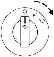
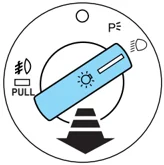
HEADLAMP CONTROL ☼
- ○ Turns the lamps off.
- P< Turns on the parking lamps, instrument panel lamps, license plate lamps and tail lamps.
- ≡D Turns the headlamps on.
Foglamp control (if equipped) ⊊
The foglamps can be turned on when the ignition is in the ON position, the headlamp control is in the P< or ≡D position and the high beams are not on.
Pull the headlamp control towards you to turn on the foglamps. The indicator light under the foglamp symbol will illuminate.
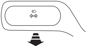
High beams ≡D
Pull the lever towards you, to the second detent, to activate. Pull the lever towards you again to deactivate.
39
Lights
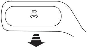
Flash to pass
Pull toward you, to the first detent, to activate and release to deactivate.
Daytime running lamps (DRL) (if equipped)
Turns the headlamps on with a reduced output. When activated, the DRL telltale is illuminated. To activate:
- the ignition must be in the ON position,
- the headlamp control is in the OFF or parking lamp position and
- the parking brake must be disengaged.
Always remember to turn on your headlamps at dusk or during inclement weather. The Daytime Running Lamp (DRL) system does not activate the tail lamps and generally may not provide adequate lighting during these conditions. Failure to activate your headlamps under these conditions may result in a collision.
PANEL DIMMER CONTROL
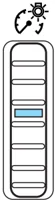
Use to adjust the brightness of the instrument panel and all applicable switches in the vehicle during headlamp and parklamp operation. Move the control to the full upright position, past detent, to turn on the interior lamps.

AIMING THE HEADLAMPS
The headlamps on your vehicle are properly aimed at the assembly plant.
40
Lights
If your vehicle has been in an accident the alignment of your headlamps should be checked by your authorized dealer.
Vertical aim adjustment
- Park the vehicle directly in front of a wall or screen on a level surface, approximately 25 feet (7.6 meters) away.
- (1) 8 feet (2.4 meters)
- (2) Center height of lamp to ground
- (3) 25 feet (7.6 meters)
- (4) Horizontal reference line
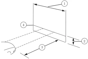
- Measure the height from the center of your headlamp to the ground and mark an 8 foot (2.4 meter) horizontal reference line on the vertical wall or screen at this height (a piece of masking tape works well). The center of the lamp is marked by a 3.0 mm circle on the headlamp lens.
- Turn on the low beam headlamps to illuminate the wall or screen and open the hood.
- On the wall or screen you will observe a flat zone of high intensity light located at the top of the beam pattern.
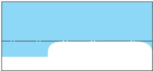
- If the top edge of the high intensity light zone is not at the horizontal reference line, the headlamp will need to be adjusted.
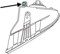
- Locate the vertical adjuster on each headlamp, then use a 7 mm Allen wrench or a Phillips screwdriver to adjust the headlamp up or down.
- HORIZONTAL AIM IS NOT REQUIRED FOR THIS VEHICLE AND IS NON-ADJUSTABLE.
- Close the hood and turn off the lamps.
41
Lights
TURN SIGNAL CONTROL ☮☯
- Push down to activate the left turn signal.
- Push up to activate the right turn signal.
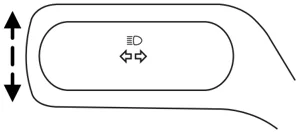
The flash rate of the turn signal will speed up considerably if the Lighting Control Module detects a left or right turn lamp bulb (front or rear) is burned out.
I NTERIOR LAMPS
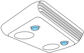
Map lamps
Press the controls on either side of the lamp to turn the light on.
BULB REPLACEMENT
Headlamp Condensation
The headlamps are vented to equalize pressure. When moist air enters the headlamp(s) through the vents, there is a possibility that condensation can occur. This condensation is normal and will clear within 45 minutes of headlamp operation.
Using the right bulbs
Replacement bulbs are specified in the chart below. Headlamp bulbs must be marked with an authorized “D.O.T.” for North America and an “E” for Europe to ensure lamp performance, light brightness and pattern and safe visibility. The correct bulbs will not damage the lamp assembly or void the lamp assembly warranty and will provide quality bulb burn time.
42
Lights
| Function | Trade Number |
|---|---|
| Headlamp | H13 |
| Park lamp, turn lamp, side marker (front) | 3157 or 3157K |
| Sidemarker (front) | W5W or W5WL |
| Fog lamp | 9145-GT or H11-Pony (if equipped) |
| Tail lamp, brakelamp, turn lamp | 3057K or 4057K |
| Sidemarker (rear) | W5W or W5WL |
| High-mount brakelamp | 921 |
| Backup lamp | 921 |
| License plate lamp | 168 |
| Overhead console/map lamp | W5W |
| All replacement bulbs are clear in color except where noted. | |
| To replace all instrument panel lights - see your authorized dealer. |
Interior bulbs
Check the operation of all bulbs frequently.
Replacing exterior bulbs
Check the operation of all the bulbs frequently.
Replacing headlamp bulbs
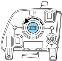
To remove the headlamp bulb:
- Make sure headlamp switch is in the OFF position, then open the hood.
- Disconnect the electrical connector from the bulb by depressing the retainer clip and pulling rearward.
- Remove the bulb by rotating it counterclockwise and pulling it straight out.
43
Lights
Handle a halogen headlamp bulb carefully and keep out of children's reach. Grasp the bulb only by its plastic base and do not touch the glass. The oil from your hand could cause the bulb to break the next time the headlamps are operated.
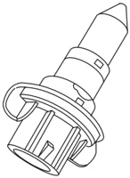
Install the new bulb in reverse order.
Replacing front turn signal bulbs
- Make sure the headlamp control is in the OFF position and open the hood.
- Locate the lamp assembly from underneath the vehicle and rotate the bulb socket counterclockwise and remove from lamp assembly.
- Pull the bulb straight out from the socket.
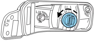
Install the new bulb in reverse order.
Replacing front parking lamp bulbs
- Make sure the headlamp control is in the OFF position and open the hood.
- Locate the lamp assembly from underneath the vehicle and rotate the bulb socket counterclockwise and remove from lamp assembly.
- Pull the bulb straight out from the socket.
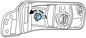
Install the new bulb in reverse order.
Replacing foglamp bulbs (if equipped)
- Make sure the headlamp control is in the OFF position and open the hood.
44
Lights
- Remove the sight shield by loosening the six fasteners with a flat head screwdriver.
- Remove the two underhood bolts attaching the bumper cover next to the grill and then pull the cover/grille/foglamp assembly forward to access the foglamp bulbs.
- Disconnect the electrical connector from the bulb by pulling it straight off.
- Rotate the bulb counterclockwise and remove from the lamp assembly. Install the new bulb in reverse order.
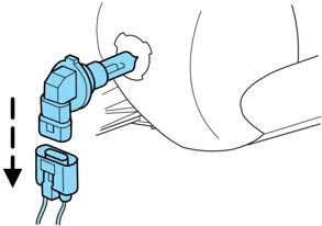
Replacing tail lamp/brake/rear turn signal lamp bulbs
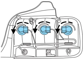
The tail lamp, the brake lamp and the turn signal lamp bulbs are located in the tail lamp assembly. Follow the same steps to replace either bulb.
- Make sure headlamp switch is in the OFF position, then open the trunk.
- Carefully remove fasteners around the lamp area and then remove the interior trunk trim.
- Disconnect the electrical grommet by pulling it straight off of the lamp assembly.
- Remove three nut and washer assemblies and the lamp assembly from the vehicle.
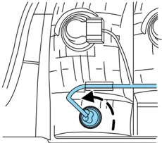
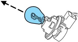
- Remove the bulb socket by rotating it counterclockwise, then pulling it out of the lamp assembly.
- Pull the bulb straight from the socket.
Install the new bulb in reverse order.
45
Lights
Replacing backup bulbs
The backup lamp is located in the tail lamp assembly. Follow the same steps to replace either bulb.
- Make sure headlamp switch is in the OFF position, then open the trunk.
- Carefully remove fasteners around the lamp area, then remove the interior trunk trim.
- Disconnect the electrical connector by pulling it straight off of the lamp assembly.
- Remove the three nut and washer assemblies and the lamp assembly from the vehicle.
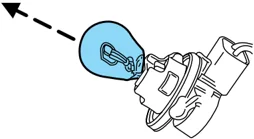
- Remove the bulb socket by rotating it counterclockwise, then pulling it out of the lamp assembly.
- Pull the bulb straight from the socket.
Install the new bulb in reverse order.
Replacing rear sidemarker lamp bulbs
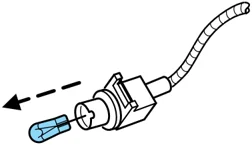
- Make sure the headlamp switch is in the OFF position and locate the sidemarker on the rear bumper fascia.
- Install a flathead screwdriver between the rear of the sidemarker lens and the bumper fascia.
- Push the screwdriver to the front of the vehicle and then slide it towards you to pop out the lens cover.
- Carefully pull the bulb straight out of socket.
Install the new bulb in reverse order.
46
Lights
Replacing high-mount brake lamp bulbs
- Make sure the headlamp switch is in the OFF position and then open the trunk.
- Inside trunk, pull the trim panel straight off of the underside of the trunk lid.
- Locate the lighting assembly and push the release tab to access the bulb socket.
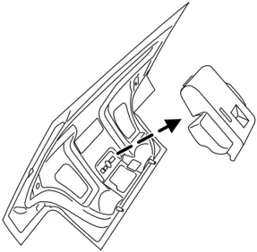
- Carefully pull the bulb straight out of socket. Install the new bulb in reverse order.
Replacing license plate lamp bulbs
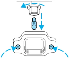
- Make sure the headlamp switch is in the OFF position, then remove the two screws and the license plate lamp assembly.
- Remove bulb socket by turning counterclockwise.
- Carefully pull the bulb out from the socket. Install new bulb(s) in reverse order.
47
Driver Controls
MULTI-FUNCTION LEVER
Windshield wiper: For intermittent operation, move control up one position.
Adjust the rotary control to the desired speed setting.
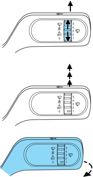
For normal or low speed wiper operation, move control up two positions from OFF.
For high speed wiper operation, move control up three positions from OFF.
Windshield washer: Pull the end of the stalk towards you:
- briefly: causes a single swipe of the wipers without washer fluid.
- a quick pull and hold: the wipers will swipe three times with washer fluid.
- a long pull and hold: the wipers and washer fluid will be activated for up to ten seconds.
Note: Do not operate the washer when the washer reservoir is empty. This may cause the washer pump to overheat. Check the washer fluid level frequently. Do not operate the wipers when the windshield is dry. This may scratch the glass, damage the wiper blades and cause the wiper motor to burn out. Before operating the wiper on a dry windshield, always use the windshield washer. In freezing weather, be sure the wiper blades are not frozen to the windshield before operating the wipers.
48
Driver Controls
TILT STEERING WHEEL (IF EQUIPPED)
To adjust the steering wheel:
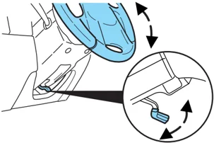
- Push the lever down to unlock the steering column. While the lever is in the down position, tilt the steering column to its desired orientation.
- While holding the steering column, pull the lever up to its original position to lock the steering column.

Never adjust the steering wheel when the vehicle is moving.
CENTER CONSOLE
Your vehicle is equipped with a variety of console features. These include:
- Dual cupholders
- Auxiliary power point (in bin)
- Coin holder slots (in bin)
- Audio input jack (in bin) (for plugging mp3 player into car stereo)
- Removeable inserts in rear cupholders for larger cups
Use only soft cups in the cupholder. Hard objects can injure you in a collision.
AUXILIARY POWER POINT (12VDC)
Power outlets are designed for accessory plugs only. Do not insert any other object in the power outlet as this will damage the outlet and blow the fuse. Do not hang any type of accessory or accessory bracket from the plug. Improper use of the power outlet can cause damage not covered by your warranty.
49
Driver Controls
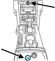
The power point is an additional power source for electrical accessories. The power points are located on the instrument panel and inside the center console storage bin.
Do not use the power point for operating the cigarette lighter element (if equipped).
To prevent the fuse from being blown, do not use the power point(s) over the vehicle capacity of 12 VDC/180W/15A.
To prevent the battery from being discharged, do not use the power point longer than necessary when the engine is not running.
Always keep the power point caps closed when not being used.
Cigarette/Cigar lighter (if equipped)
Do not plug optional electrical accessories into the cigarette lighter socket.
Do not hold the lighter in with your hand while it is heating, this will damage the lighter element and socket. The lighter will be released from its heating position when it is ready to be used.
Improper use of the lighter can cause damage not covered by your warranty.
POWER WINDOWS
! Do not leave children unattended in the vehicle and do not let children play with the power windows. They may seriously injure themselves.
! When closing the power windows, you should verify they are free of obstructions and ensure that children and/or pets are not in the proximity of the window openings.
50
Driver Controls
Press and pull the switches to open and close windows.
- Push down (to the first detent) and hold the switch to open.
- Pull up (to the first detent) and hold the switch to close.
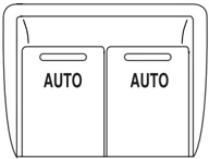
Express down (One Touch Down, Front windows only)
Allows the driver and passenger's window to open fully without holding the control down. Push the switch completely down to the second detent and release quickly. The window will open fully. Momentarily press the switch to any position to stop the window operation.
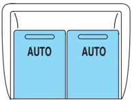
Express Up (One Touch Up, Front windows only)
Allows the driver and passenger's window to close fully without holding the control up. Pull the switch completely up to the second detent and release quickly. The window will close fully. Momentarily press the switch to any position to stop the window operation
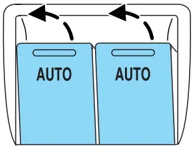
Restoring the Express up functionality (Front windows only)
Under low battery power conditions, Express Up only functionality may be lost. To reset this function after restoring full battery power, pull the switch to the Express Up position, hold the switch until the glass reaches the stall position and continue to hold for 2 seconds. Push the window switch DOWN and operate the window to the full down position. Express UP will now be functional. Perform Express UP re-calibration with door closed only. Calibrating with door open will cause the window to continuously bounce back.
Accessory delay
With accessory delay, the window switches and radio may be used for up to ten minutes after the ignition switch is turned to the OFF position or until any door or trunk is opened.
51
Driver Controls
Bounce Back (Front windows only)
When an obstacle has been detected in the window opening as the window is moving upward, the window will automatically move down and stop at a prescribed position.
Bounce Back Override (Front windows only)
To override Bounce Back, within 2 seconds after reaching Bounce Back position, if the switch is moved from the Neutral to the Express Up position the window will travel up with no bounce back protection. If the switch is released before the window reaches fully closed position, the window will stop. For example: Bounce Back Override can be used to overcome the resistance of ice on the window or seals.
Short drop glass (Front windows only)
In order to improve door efforts and sealing, your vehicle is equipped with short drop glass. This feature lowers the glass when either door is opened. The glass returns to its closed position when the door is closed.
Proper operation of the short drop glass requires that the windows be calibrated. Though your windows will have been calibrated before your vehicle is delivered to you, it is possible for the windows to lose calibration. If a window loses its calibration, your short drop feature will lower the window, but will not raise it again when the door is closed. To re-calibrate the window, pull the switch up to raise the window until it completes its travel and hold the switch up for 2 seconds. Another possible effect of lost calibration is that the feature may not lower the window. To re-calibrate the window in this case, lower the window until it completes its travel and hold the switch down for 2 seconds. Immediately after releasing the window down switch, pull the switch up to raise the window until it completes its travel and hold the switch up for 2 seconds. Perform Short drop re-calibration with doors closed only. Re-Calibrating with doors open will cause the window to continuously bounce back.
Rear Power Windows (Convertible Only)
The rear quarter windows are operated by a single window switch located at the Driver door window controls. Press and pull the window switch to open and close the windows.
• Push down and hold the switch to open.
• Pull up and hold the switch to close.
52
Driver Controls
AUTOMATIC DIMMING INSIDE REAR VIEW MIRROR (IF EQUIPPED)
Your vehicle is equipped with an inside rear view mirror which has an auto-dimming function. The electrochromic day/night mirror will change from the normal (high reflective) state to the non-glare (darkened) state when bright lights (glare) reach the mirror. When the mirror detects bright light from front or behind, it will automatically adjust (darken) to minimize glare.
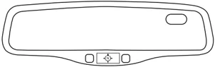
The mirror will automatically return to the normal state whenever the vehicle is placed in R (Reverse)(when the mirror is on) to ensure a bright clear view when backing up.
Do not block the sensor on the backside of the mirror since this may impair proper mirror performance.
Electronic compass (if equipped)
The compass reading will remain accurate during most driving conditions. The compass is continuously re-calibrating due to changing magnetic fields and subtle, slow changes in vehicle magnetics which can occur over the life of the vehicle. If heading appears inaccurate re-calibrate mirror, refer to Compass calibration adjustment.
The compass reading will remain fixed when significant levels of magnetic interference are experienced (such as steel bridges). The compass will return to normal operation upon leaving the magnetized area.
If highly magnetized items (such as magnetic mount antennas) are placed very near the compass the display will change to “C”. If a “C” is displayed, remove the source of magnetic interference and re-calibrate compass, refer to Compass calibration adjustment.
Most geographic areas (zones) have a magnetic north compass point that varies slightly from the northerly direction on maps. A correct zone setting will eliminate this error. You MUST set the mirror to the proper zone to get an accurate compass reading, refer to Compass zone adjustment.
53
Driver Controls
Compass zone adjustment
- Determine which compass zone you are in by referring to the zone map.
- Turn the ignition to the ON/RUN position.
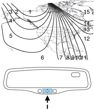
- Press and hold the control for no more than six seconds until the zone selection number appears in the mirror display window. If a “C” appears repeat this step.
- Release the control, then press it down again.
- Repeatedly press until your zone number is shown in the mirror display, then release.
- The display will show all segments, then return to normal compass mode within ten seconds.
Compass calibration adjustment
Perform this adjustment in an open area free from steel structures and high voltage lines.
- Start the vehicle.
- Press and hold the control until “C” appears in the mirror display.
- Drive the vehicle slowly (less than 3 mph [5 km/h]) in circles until the display reads a direction.
- The compass is now calibrated.
54
Driver Controls
EXTERIOR MIRRORS
Power side view mirrors
To adjust your mirrors:
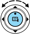
- Rotate the control clockwise to adjust the right mirror and rotate the control counterclockwise to adjust the left mirror.
- Move the control in the direction you wish to tilt the mirror.
- Return to the center position to lock mirrors in place.
SPEED CONTROL
With speed control set, you can maintain a speed of 30 mph (48 km/h) or more without keeping your foot on the accelerator pedal. Speed control does not work at speeds below 30 mph (48 km/h).
Do not use the speed control in heavy traffic or on roads that are winding, slippery or unpaved.
Setting speed control
The controls for using your speed control are located on the steering wheel for your convenience.
- Press the ON control and release it.
- Accelerate to the desired speed.
- Press the SET + control and release it.
- Take your foot off the accelerator pedal.
- The indicator light on the instrument cluster will turn on.
Note:
- Vehicle speed may vary momentarily when driving up and down a steep hill.
- If the vehicle speed increases above the set speed on a downhill, you may want to apply the brakes to reduce the speed.
55


Driver Controls
- If the vehicle speed decreases more than 10 mph (16 km/h) below your set speed on an uphill, your speed control will disengage.
- If the vehicle speed decreases to 30 mph (48 km/h) or less, your speed control will disengage
Disengaging speed control
To disengage the speed control:
- Depress the brake pedal or clutch pedal (if equipped)
Disengaging the speed control will not erase previous set speed.
Resuming a set speed
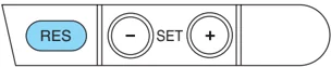
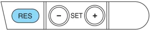
Press the RES (resume) control and release it. This will automatically return the vehicle to the previously set speed. The RES control will not work if the vehicle speed is not faster than 30 mph (48 km/h).
Increasing speed while using speed control
There are three ways to set a higher speed:
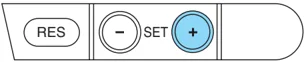
- Press and hold the SET + control until you get to the desired speed, then release the control.
- Press and release the SET + control to operate the Tap-Up function. Each tap will increase the set speed by 1 mph (1.6 km/h).
- Use the accelerator pedal to get to the desired speed. When the vehicle reaches that speed press and release the SET + control.
Reducing speed while using speed control
There are three ways to reduce a set speed:
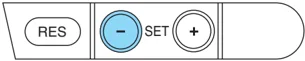
- Press and hold the SET - control until you get to the desired speed, then release the control.
- Press and release the SET - control to operate the Tap-Down function. Each tap will decrease the set speed by 1 mph (1.6 km/h).
56
Driver Controls
- Depress the brake pedal until the desired vehicle speed is reached, press the SET + control.

Turning off speed control
There are two ways to turn off the speed control:
- Press the speed control OFF control.
- Turn OFF the ignition.
Note: When you turn off the speed control or the ignition, your speed control set speed memory is erased.
CONVERTIBLE (IF EQUIPPED)
Do not store articles behind rear seat. Articles stored in the convertible top stowage compartment may break the rear glass window when the top is lowered.
Lowering the convertible top
The convertible top can be lowered with the side windows down. The windows will automatically lower when lowering or raising the top.
The convertible top will not operate unless the vehicle is traveling under 3.1 mph (5 km/h). Do not lower the top when the top material is wet.
To lower the convertible top:
- Bring vehicle to a complete stop. Key must be in the ON position. It is recommended that the vehicle's engine is running when lowering the top to prevent draining the battery.
- Check the convertible top stowage compartment behind the rear seat to be sure it is empty and ready to receive the top. Check the convertible top outer surface to be sure it is free of leaves and debris.
57
Driver Controls
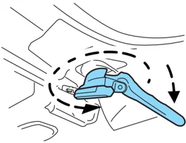
The latch handles must be pulled downwards fully to allow the latch to fully rotate into the open position
- Unclamp the top from the windshield header by pulling each latch handle down and then rotating the latch to the rear until it clears the header.
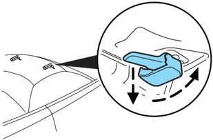
Note: If the top has not been lowered for some time and sticks to the windshield header, push the front of the top up slightly with your hand to loosen it.
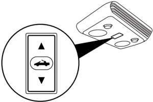
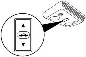
- Push the convertible top switch on the overhead console and hold until the windows are completely down and the top is completely stored.
58
Driver Controls
Installation of the boot (if equipped)
Be sure the boot is secure on the vehicle before driving.
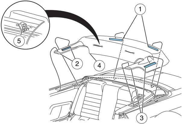
- Install the boot on the vehicle by hooking the boot retaining clips on the back panel.
- Install the boot on the right side tucking in the front part of the boot in the quarter panel and hooking the retaining clip on the side.
- Install the boot on the left side tucking in the front part of the boot in the quarter panel and hooking the retaining clip on the side.
- Tuck the boot corners behind the shoulder belts.
- Secure the boot straps on the rear seat hooks behind the rear seat.
Note: Improper installation can result in loss and/or damage of the boot while driving.
Always secure the retaining clips and boot straps on the vehicle or the boot may come loose while driving.
To remove, unhook the boot straps from the rear seat hooks and push the boot down slightly unhooking the boot retaining clips from the vehicle and lift off.
59
Driver Controls
Storing the boot
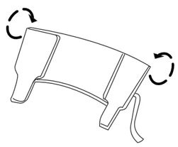
- Position the boot right-side up and fold each side of the boot inward.
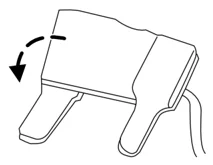
- Turn the boot upside down and fold the left side of the boot inward.
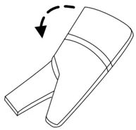
- Fold the right side inward and secure the boot with the strap. Stow the boot in the trunk.
Raising the convertible top
The convertible top will not operate unless the vehicle is traveling under 3.1 mph (5 km/h).
60
Driver Controls
To raise the convertible top:
- Bring the vehicle to a complete stop. Key must be in the ON position. It is recommended that the vehicle’s engine is running when raising the top to prevent draining the battery.
- Push the convertible top switch, holding it until the windows lower completely and the top unfolds and moves forward toward the windshield header.
- You can release the convertible top switch to open both latch handles before the top meets the windshield header. Make sure the latch handles are pulled down fully for hand clearance and are swung to the fully open position.
Note: If the top has been in the down position for an extended period or if the temperature is low, the top material may shrink a small amount. Pulling down on the latch handles and at the center grip in the header will make it easier to fasten the top.
- Continue to use the convertible top switch to raise the top until it has reached the fully closed position flush to the header.
Note: The two pins under the forward edge of the top should seat themselves in the matching holes in the header.
The latch handles must be pulled downwards fully to allow the latch to fully rotate into the closed position.
-
Secure the Driver’s side latch first then secure the Passenger side. Pull down firmly on the latch handles before rotating them into the windshield header until they reach the full forward position. Pulling down on the latch handles and at the center grip in the header will make it easier to fasten the top. Push the latch handles up into the stowed position once the latch is rotated into the full forward position.
-
Raise the front and rear side windows.
61
Driver Controls
MESSAGE CENTER (IF EQUIPPED)
With the ignition in the ON position, the message center, located on your instrument cluster, displays important vehicle information through a constant monitor of vehicle systems. You may select display features on the message center for a display of status. The system will also notify you of potential vehicle problems with a display of system warnings followed by a long indicator chime.
Note: Refer to the SETUP menu in this section to select the Single or Dual mode display in your message center.
Selectable features
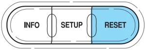
Reset
Press this control to select and reset functions shown in the INFO menu and SETUP menu.
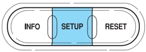
Setup menu
Press this control for the following displays:
- System Check
- Display Color
- Units (English/Metric)
- Display Mode
- Language
System check
Selecting this function from the SETUP menu causes the message center to cycle through each of the systems being monitored. For each of the monitored systems, the message center will indicate either an OK message or a warning message for two seconds.
62
Driver Controls
Pressing the RESET control cycles the message center through each of the systems being monitored.
The sequence of the system check report and how it appears in the message center is as follows:
- OIL PRESSURE
- CHARGING SYSTEM
- DRIVER DOOR
- PASSENGER DOOR
- TRUNK
- BRAKE SYSTEM
- SECURITY SYSTEM (if equipped)
- TRAC CONTROL (if equipped)
- FUEL CAP
- FUEL LEVEL
- MILES TO EMPTY
Display color
The instrument cluster gauges are backlit with white backlighting when the headlamps are off. When the headlamps are on, the user can select one of six preset colors or one user definable color (MyColor™) for the nighttime gauge backlighting. Headlamps must be on to set up the nighttime display color.
Note: A gauge in a warning condition will be lit red when the headlamps are on.
- Press SETUP to get to the DISPLAY COLOR set up menu.
- Pressing RESET will scroll through the following selectable colors:
Green \hfill Blue Purple \hfill White Orange \hfill Red MyColor \hfill Adjust (to define MyColor)
63
Driver Controls
Adjusting MyColor™: MyColor™ is a user defined backlighting color. The backlighting colors are achieved through the blending of light from Red, Green, and Blue LEDs. Apart from the 6 preset colors, drivers can create their own color by adjusting the levels of the three primary colors through the MyColor™ feature to achieve any of 125 different combinations.
The vehicle must be stationary to enter the MyColor™ adjust mode. To enter the MyColor™ adjust mode, hold RESET for 3 seconds at the Adjust menu, or press SETUP to scroll though the display colors again. When in the MyColor™ adjust mode, pressing RESET will step through the Red, Green, Blue and Exit options. Pressing SETUP will increment the proportion of the color being adjusted. Try many combinations and record your favorites. To Save and Exit MyColor™ adjust hold RESET for 3 seconds when prompted. Pressing RESET for less than 3 seconds will cycle back through the color components.
Units (English/Metric)
- Select this function from the SETUP menu for the current units to be displayed.
- Press the RESET control to change from English to Metric.
Display Mode
- Select this function from the SETUP menu to select the Display Mode.
- Single Mode will display only the selected function. Dual Mode will display the selected function and the odometer.
Language
- Select this function from the SETUP menu for the current language to be displayed.
64
Driver Controls
- Pressing the RESET control cycles the message center through each of the language choices.
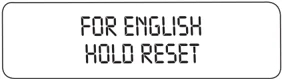
- Press and hold the RESET control to set the language choice.
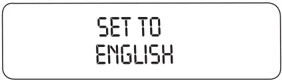
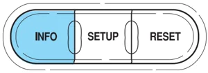
Info menu
This control displays the following control displays:
- Odometer
- Trip odometer
- Distance to Empty
- Average Fuel Economy
- Instantaneous Fuel Economy
- Fuel Used
- Trip Elapsed Drive Time
- Average Speed
- Blank Display
Odometer/Trip odometer
Refer to Gauges in the Instrument Cluster chapter.
Distance to empty (DTE)
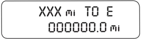
Selecting this function from the INFO menu estimates approximately how far you can drive with the fuel remaining in your tank under normal driving conditions. Remember to turn the ignition OFF when refueling to allow this feature to correctly detect the added fuel.
Single mode display
XXX mi TO E 000000.0 mi
65
Driver Controls
Dual mode display
The DTE function will display LOW FUEL LEVEL and sound a tone for one second when you have approximately 50 miles (80 km) to empty. If you RESET this warning message, this display and tone will return within 10 minutes.
DTE is calculated using a running average fuel economy, which is based on your recent driving history of 500 miles (800 km). This value is not the same as the average fuel economy display. The running average fuel economy is reinitialized to a factory default value if the battery is disconnected.
Average fuel economy (AFE)
Select this function from the INFO menu to display your average fuel economy in miles/gallon or liters/100 km.
If you calculate your average fuel economy by dividing miles traveled by gallons of fuel used (liters of fuel used by 100 kilometers traveled), your figure may be different than displayed for the following reasons:
- Your vehicle was not perfectly level during fill-up
- Differences in the automatic shut-off points on the fuel pumps at service stations
- Variations in top-off procedure from one fill-up to another
- Rounding of the displayed values to the nearest gallon (0.1 liter)
- Drive the vehicle at least 5 miles (8 km) with the speed control system engaged to display a stabilized average.
- Record the highway fuel economy for future reference.
It is important to press the RESET control after setting the speed control to get accurate highway fuel economy readings.
66
Driver Controls
Instantaneous fuel economy Select this function from the INFO menu to display your instantaneous fuel economy. This will display your fuel economy as a Bar Graph ranging from ▼ poor economy to ▲ excellent economy.

Your vehicle must be moving to calculate instantaneous fuel economy. When your vehicle is not moving, this function shows ▼, one or no bars illuminated. Instantaneous fuel economy cannot be reset.
Fuel Used Select this function from the INFO menu to display the fuel used since last reset. The information displayed will be in gallons or liters, depending on English/Metric mode state.
Trip elapsed drive time Select this function from the INFO menu to display a timer. Trip elapsed drive time will only accumulate time when the ignition is in the Run/Start position.
To operate the Trip Elapsed Drive Time perform the following:
- Press and release RESET in order to start the timer.
- Press and release RESET to pause the timer.
- Press and hold RESET for 2 seconds in order to reset the timer.
Average speed Select this function from the INFO menu to display average speed since last reset.
Blank Display Select this function from the INFO control to turn your message center display OFF.
67
Driver Controls
System warnings
System warnings alert you to possible problems or malfunctions in your vehicle’s operating systems.
In the event of a multiple warning situation, the message center will cycle the display to show all warnings by displaying each one for 4 seconds.
The message center will display the last selected feature if there are no more warning messages. This allows you to use the full functionality of the message center after you acknowledge the warning by pressing the RESET control and clearing the warning message.
Warning messages that have been reset are divided into three categories:
- They will not disappear until a condition is changed.
- They will reappear on the display ten minutes from the reset.
- They will not reappear until an ignition OFF-ON cycle has been completed.
This acts as a reminder that these warning conditions still exist within the vehicle.
| Warning display | Status |
|---|---|
| Driver’s door ajar | Warning cannot be reset |
| Passenger door ajar | |
| Low oil pressure | Warning returns after 10 minutes |
| Check charging system | |
| Check traction control™ | |
| Check fuel cap | |
| Low fuel level | |
| Check brake system | Warning returns after the ignition key is turned from OFF to ON. |
| Low tire pressure | |
| Tire pressure monitor fault | |
| Tire pressure sensor fault | |
| Security event occurred | |
| Low brake fluid level |
DRIVER’S DOOR AJAR. Displayed when the driver’s door is not completely closed.
PASSENGER DOOR AJAR. Displayed when the passenger side door is not completely closed.
68
Driver Controls
TRUNK AJAR. Displayed when the trunk is not completely closed.
LOW FUEL LEVEL. Displayed as an early reminder of a low fuel condition.
CHECK CHARGING SYSTEM. Displayed when the electrical system is not maintaining proper voltage. If you are operating electrical accessories when the engine is idling at a low speed, turn off as many of the electrical loads as soon as possible. If the warning stays on or comes on when the engine is operating at normal speeds, have the electrical system checked as soon as possible.
PARK BRAKE ON. Displayed when the manual park brake is set. If the warning stays on after the park brake is released, contact your authorized dealer as soon as possible.
CHECK BRAKE SYSTEM. Displayed when the braking system is not operating properly. If the warning stays on or continues to come on, contact your authorized dealer as soon as possible.
LOW TIRE PRESSURE. Displayed when one or more tires on your vehicle have low tire pressure. Refer to Inflating Your Tires in the Tires, Wheels and Loading chapter.
TIRE PRESSURE MONITOR FAULT. Displayed when the Tire Pressure Monitoring System is malfunctioning. If the warning stays on or continues to come on, have the system inspected by your authorized dealer.
TIRE PRESSURE SENSOR FAULT. Displayed when a tire pressure sensor is malfunctioning, or your spare tire is in use. For more information on how the system operates under these conditions, refer to Understanding Your Tire Pressure Monitoring System in the Tires, Wheels and Loading chapter. If the warning stays on or continues to come on, have the system inspected by your authorized dealer
LOW BRAKE FLUID LEVEL. Indicates the brake fluid level is low and the brake system should be inspected immediately. Refer to Brake fluid reservoir in the Maintenance and Specifications chapter.
LOW OIL PRESSURE. Displayed when the engine oil pressure is low. If this warning message is displayed, check the level of the engine oil. Refer to Engine oil in the Maintenance and Specifications chapter for information about adding engine oil. If the oil level is OK and this warning persists, shut down the engine immediately and contact your authorized dealer for service.
CHECK FUEL CAP. Displayed when the fuel filler cap is not properly installed. Check the fuel filler cap for proper installation. Refer to Fuel filler cap under the Fuel Information section in the Maintenance and Specifications chapter.
69
Driver Controls
CHECK TRACTION CONTROL™. Displayed when the Traction Control™ system is not operating properly. If this message is displayed on the message center the Traction Control™ system will be partially operable. If this warning stays on, contact your authorized dealer for service as soon as possible. For further information, refer to Traction control™ in the Driving chapter.
SECURITY EVENT OCCURRED (if equipped). Displayed when the active anti-theft system (if equipped) was activated since the prior ignition cycle.
TURN SIGNAL ON REMINDER. Displayed when the turn signal is activated and the vehicle is driven more that 1/2 mile (0.8 km).
POSITIVE RETENTION FLOOR MAT (IF EQUIPPED)
! Do not install additional floor mats on top of the factory installed floor mats as they may interfere with the accelerator or the brake pedals.
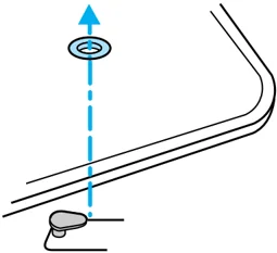
Position the floor mat so that the eyelet is over the pointed end of the retention post and rotate forward to lock in. Make sure that the mat does not interfere with the operation of the accelerator or the brake pedal. To remove the floor mat, reverse the installation procedure.

70