Roadside Emergencies
ROADSIDE ASSISTANCE
Getting roadside assistance
To fully assist you should you have a vehicle concern, Ford Motor Company offers a complimentary roadside assistance program. This program is separate from the New Vehicle Limited Warranty. The service is available:
• 24-hours, seven days a week
• for the New Vehicle Limited Warranty period of three years or 36,000 miles (60,000 km), whichever occurs first on Ford and Mercury vehicles, and four years or 50,000 miles (80,000 km) on Lincoln vehicles.
Roadside assistance will cover:
• a flat tire change with a good spare (except Ford GT which has a tire inflation kit)
• battery jump start
• lock-out assistance (key replacement cost is the customer's responsibility)
• fuel delivery – Independent Service Contractors, if not prohibited by state, local or municipal law shall deliver up to 2.0 gallons (7.5L) of gasoline or 5 gallons (18.9L) of diesel fuel to a disabled vehicle. Fuel delivery service is limited to two no-charge occurrences within a 12-month period.
• winch out – available within 100 feet (30.5 meters) of a paved or county maintained road, no recoveries.
• towing – Ford/Mercury/Lincoln eligible vehicle towed to an authorized dealer within 35 miles (56.3 km) of the disablement location or to the nearest authorized dealer. If a member requests to be towed to an authorized dealer more than 35 miles (56.3 km) from the disablement location, the member shall be responsible for any mileage costs in excess of 35 miles (56.3 km).
Trailers shall be covered up to $100 if the disabled eligible vehicle requires service at the nearest authorized dealer. If the trailer is disabled, but the towing vehicle is operational, the trailer does not qualify for any roadside services.
173
Roadside Emergencies
Canadian customers refer to your Owner Information Guide for information on:
• coverage period • exact fuel amounts • towing of your disabled vehicle • emergency travel expense reimbursement • travel planning benefits
Using roadside assistance
Complete the roadside assistance identification card and place it in your wallet for quick reference. In the United States, this card is found in the Owner Guide portfolio in the glove compartment. In Canada, the card is found in the Owner Information Guide in the glove compartment.
U.S. Ford or Mercury vehicle customers who require roadside assistance, call 1–800–241–3673; Lincoln vehicle customers call 1–800–521–4140.
Canadian customers who require roadside assistance, call 1–800–665–2006.
If you need to arrange roadside assistance for yourself, Ford Motor Company will reimburse a reasonable amount. To obtain reimbursement information, U.S. Ford or Mercury vehicles customers call 1–800–241–3673; Lincoln vehicle customers call 1–800–521–4140.
Canadian customers who need to obtain reimbursement information, call 1–800–665–2006.
Roadside coverage beyond basic warranty
In the United States, you may purchase additional roadside assistance coverage beyond this period through the Ford Auto Club by contacting your authorized dealer.
Similarly in Canada, for uninterrupted Roadside Assistance coverage, you may purchase extended coverage prior to your Basic Warranty’s Roadside Assistance expiring. For more information and enrollment, contact 1–877–294–2582 or visit our website at www.ford.ca.
174
Roadside Emergencies
HAZARD FLASHER CONTROL
The hazard flasher is located on the instrument panel by the radio. The hazard flashers will operate when the ignition is in any position or if the key is not in the ignition.

Push in the flasher control and all front and rear direction signals will flash. Press the flasher control again to turn them off. Use it when your vehicle is disabled and is creating a safety hazard for other motorists.
Note: With extended use, the flasher may run down your battery.
FUEL PUMP SHUT-OFF SWITCH
This device stops the electric fuel pump from sending fuel to the engine when your vehicle has had a substantial jolt.
After an accident, if the engine cranks but does not start, this switch may have been activated.
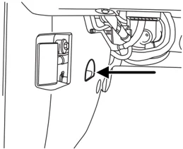
The fuel pump shut-off switch is located in the driver's footwell, by the hood release
To reset the switch:
- Turn the ignition OFF.
- Check the fuel system for leaks.
- If no leaks are apparent, reset the switch by pushing in on the reset button.
- Turn the ignition ON.
- Wait a few seconds and return the key to OFF.
- Make another check for leaks.
175
Roadside Emergencies
FUSES AND RELAYS
Fuses
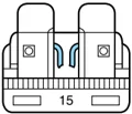
If electrical components in the vehicle are not working, a fuse may have blown. Blown fuses are identified by a broken wire within the fuse. Check the appropriate fuses before replacing any electrical components.
Note: Always replace a fuse with one that has the specified amperage rating. Using a fuse with a higher amperage rating can cause severe wire damage and could start a fire.
Standard fuse amperage rating and color
| Fuse rating | Mini fuses | Standard fuses | Maxi fuses | Cartridge maxi fuses | Fuse link cartridge |
|---|---|---|---|---|---|
| 2A | Grey | Grey | — | — | — |
| 3A | Violet | Violet | — | — | — |
| 4A | Pink | Pink | — | — | — |
| 5A | Tan | Tan | — | — | — |
| 7.5A | Brown | Brown | — | — | — |
| 10A | Red | Red | — | — | — |
| 15A | Blue | Blue | — | — | — |
| 20A | Yellow | Yellow | Yellow | Blue | Blue |
| 25A | Natural | Natural | — | — | — |
| 30A | Green | Green | Green | Pink | Pink |
| 40A | — | — | Orange | Green | Green |
| 50A | — | — | Red | Red | Red |
| 60A | — | — | Blue | — | Yellow |
| 70A | — | — | Tan | — | Brown |
| 80A | — | — | Natural | — | Black |
176
Roadside Emergencies
Passenger compartment fuse panel
The fuse panel is located in the lower passenger side area behind the kick panel. Remove the trim panel cover and the fuse cover to access the fuses.
To remove a fuse use the fuse puller tool provided to the left of the fuses and relays.
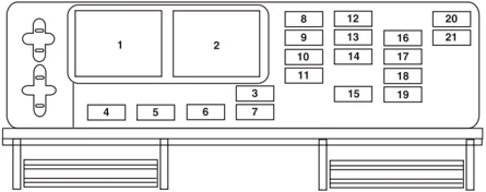
The fuses are coded as follows:
Roadside Emergencies
| Fuse/Relay Location | Fuse Amp Rating | Passenger Compartment Fuse Panel Description |
|---|---|---|
| 14 | 5A | A/C cycle switch |
| 15 | 10A | Brake On/Off (BOO) power |
| 16 | 5A | Cluster |
| 17 | 10A | Restraint Control Module (RCM), Passenger Occupant Detection System (PODS), Passenger Airbag Deactivation Indicator (PADI) |
| 18 | 10A | Anti-lock Brake System (ABS) |
| 19 | 5A | Powertrain Control Module (PCM) relay, Passive Anti-Theft System (PATS), Instrument cluster airbag warning lamp |
| 20 | 10A | Radio (Start) |
| 21 | 10A | Starter relay |
Power distribution box
The power distribution box is located in the engine compartment. The power distribution box contains high-current fuses that protect your vehicle’s main electrical systems from overloads.
Do not probe the contacts for the fuses and relays in the power distribution box as damage will occur, causing improper, or loss of, electrical functionality.
⚠ Always disconnect the battery before servicing high current fuses.
⚠ To reduce risk of electrical shock, always replace the cover to the Power Distribution Box before reconnecting the battery or refilling fluid reservoirs.
If the battery has been disconnected and reconnected, refer to the Battery section of the Maintenance and Specifications chapter.
178
Roadside Emergencies
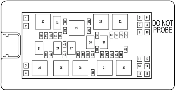
The high-current fuses are coded as follows.
Roadside Emergencies
| Fuse/Relay Location | Fuse Amp Rating | Power Distribution Box Description |
|---|---|---|
| 14 | 30A* | Driver seat |
| 15 | 30A* | Passenger seat |
| 16 | 30A* | Front amplifier (Shaker 500 radio) |
| 20 | Mini relay | PCM |
| 21 | Micro relay | Fuel pump |
| 22 | Mini relay | Starter |
| 23 | — | Not used |
| 24 | Micro relay | A/C clutch |
| 25 | Mini relay | Cooling fan (High-speed) |
| 26 | Mini relay | Horn |
| 27 | Micro relay | High beams |
| 28 | Mini relay | Cooling fan (Low-speed) |
| 29 | Mini relay | Rear defroster |
| 30 | Micro relay | Fog lamps |
| 31 | Mini relay | Convertible top (Up) |
| 32 | Mini relay | Climate control blower |
| 33 | Mini relay | Convertible top (Down) |
| 34 | Micro relay | Decklid |
| 39 | 15A** | Engine #4 |
| 40 | 15A** | Engine #2 |
| 41 | 15A** | Fuel pump |
| 42 | 15A** | Engine #3 |
| 43 | 10A** | Alternator |
| 44 | 10A** | Delayed accessory |
| 45 | 10A** | PCM |
| 46 | 25A** | Horn |
| 47 | 15A** | Engine #1 |
| 48 | Diode | A/C clutch |
| 49 | 15A** | A/C clutch |
| 50 | 15A** | High beams |
180
Roadside Emergencies
| Fuse/Relay Location | Fuse Amp Rating | Power Distribution Box Description |
|---|---|---|
| 51 | 10A** | Convertible top |
| 52 | 30A** | Rear defroster |
| 53 | Diode | PCM |
| 54 | — | Not used |
| 55 | — | Not used |
| 56 | 20A** | Radio, SDARS |
| 57 | 20A** | Decklid release |
| 58 | 15A** | Fog lamps |
| 59 | 30A** | SJB #5 (Passenger compartment fuse box) |
| 60 | — | Not used |
| 61 | 20A** | Power point #1 (Instrument panel) |
| 62 | 20A** | SJB #7 (Passenger compartment fuse box) |
| 63 | 30A** | SJB #6 (Passenger compartment fuse box) |
| 64 | 20A** | Power point #2 (Console) |
| 65 | 30A** | ABS #2 |
| 66 | 25A** | Heated seats |
| 67 | 30A** | SJB #4 (Passenger compartment fuse box) |
| 68 | 20A** | Ignition |
| * Cartridge Fuses ** Mini Fuses |
Auxiliary relay
On heated seat equipped vehicles, there is a relay box located behind the headlamp switch area containing two micro relays for the driver and passenger heated seats.
CHANGING A FLAT TIRE
If you get a flat tire while driving:
- do not brake heavily.
- gradually decrease the vehicle’s speed.
181
Roadside Emergencies
- hold the steering wheel firmly.
- slowly move to a safe place on the side of the road.
Your vehicle may be equipped with a conventional spare tire that is different in one or more of the following: type, brand, size, speed rating and tread design. If this is the case, this dissimilar spare tire is still rated for your vehicle loads (GAWR and GVWR). This temporary spare tire is not equipped with a Tire Pressure Monitor System (TPMS) sensor.
The use of tire sealants may damage your tires. The use of tire sealants may also damage your Tire Pressure Monitoring System and should not be used.
Refer to Tire Pressure Monitoring System (TPMS) in the Tire, Wheels and Loading chapter for important information. If the tire pressure monitor sensor becomes damaged, it will no longer function.
Dissimilar spare tire/wheel information
Failure to follow these guidelines could result in an increased risk of loss of vehicle control, injury or death.
If you have a dissimilar spare tire/wheel, then it is intended for temporary use only. This means that if you need to use it, you should replace it as soon as possible with a road tire/wheel that is the same size and type as the road tires and wheels that were originally provided by Ford. If the dissimilar spare tire or wheel is damaged, it should be replaced rather than repaired.
A dissimilar spare tire/wheel is defined as a spare tire and/or wheel that is different in brand, size or appearance from the road tires and wheels and can be one of three types:
- T-type mini-spare: This spare tire begins with the letter “T” for tire size and may have “Temporary Use Only” molded in the sidewall
- Full-size dissimilar spare with label on wheel: This spare tire has a label on the wheel that states: “THIS TIRE AND WHEEL FOR TEMPORARY USE ONLY”
When driving with one of the dissimilar spare tires listed above, do not:
- Exceed 50 mph (80 km/h)
182
Roadside Emergencies
- Load the vehicle beyond maximum vehicle load rating listed on the Safety Compliance Label
- Tow a trailer
- Use snow chains on the end of the vehicle with the dissimilar spare tire
- Use more than one dissimilar spare tire at a time
- Use commercial car washing equipment
- Try to repair the dissimilar spare tire
Use of one of the dissimilar spare tires listed above at any one wheel location can lead to impairment of the following:
- Handling, stability and braking performance
- Comfort and noise
- Ground clearance and parking at curbs
- Winter weather driving capability
- Wet weather driving capability
For vehicles equipped with 4WD, it is not recommended that the vehicle be operated in 4WD modes with a temporary emergency spare tire. If 4WD operation is necessary, do not operate above speeds of 10 mph (16 km/h) or for distances above 50 miles (80 km).
3. Full-size dissimilar spare without label on wheel
When driving with the full-size dissimilar spare tire/wheel, do not:
- Exceed 70 mph (113 km/h)
- Use more than one dissimilar spare tire/wheel at a time
- Use commercial car washing equipment
- Use snow chains on the end of the vehicle with the dissimilar spare tire/wheel
The usage of a full-size dissimilar spare tire/wheel can lead to impairment of the following:
- Handling, stability and braking performance
- Comfort and noise
- Ground clearance and parking at curbs
- Winter weather driving capability
- Wet weather driving capability
183
Roadside Emergencies
- All-Wheel driving capability (if applicable)
- Load leveling adjustment (if applicable)
When driving with the full-size dissimilar spare tire/wheel additional caution should be given to:
- Towing a trailer
- Driving vehicles equipped with a camper body
- Driving vehicles with a load on the cargo rack
Drive cautiously when using a full-size dissimilar spare tire/wheel and seek service as soon as possible.
How to change a flat tire
Note: If your vehicle is equipped with the tire pressure monitoring system (TPMS), the system indicator light will illuminate when the spare is in use. To restore the full functionality of the TPMS system, all road wheels equipped with the tire pressure monitoring sensors must be mounted on the vehicle.
If your vehicle is equipped with TPMS, have a flat tire serviced by an authorized dealer in order to prevent damage to the TPMS sensor, refer to Tire pressure monitoring system (TPMS) in the Tires, Wheels and Loading chapter. Replace the spare tire with a road tire as soon as possible.
To help prevent the vehicle from moving when you change a tire, be sure the parking brake is set, then block (in both directions) the wheel that is diagonally opposite (other side and end of the vehicle) to the tire being changed.
If the vehicle slips off the jack, you or someone else could be seriously injured.
Do not attempt to change a tire on the side of the vehicle close to moving traffic. Pull far enough off the road to avoid the danger of being hit when operating the jack or changing the wheel.
Before changing the tire:
- Park on a level surface.
- Activate the hazard flashers.
184
Roadside Emergencies
- Place the gearshift lever in P (Park) (automatic transmission) or R (Reverse) (manual transmission).
- Set the parking brake.
- Turn off the ignition.
To change the tire:
Note: Passengers should not remain in the vehicle when the vehicle is being jacked.
- Block both the front and rear of the wheel diagonally opposite the flat tire. For example, if the left front tire is flat, block the right rear wheel.
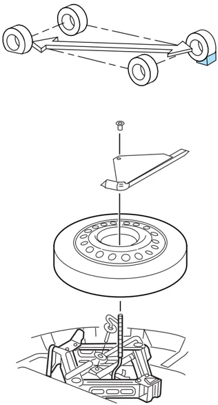
- Remove the lug wrench, spare tire and jack.
185
Roadside Emergencies
- Remove the center ornament (if equipped) from the wheel. Loosen each wheel lug nut one-half turn counterclockwise but do not remove them until the wheel is raised off the ground.
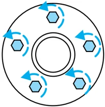
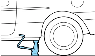
- Put the jack in the jack notch next to the tire you are changing. Turn the jack handle clockwise until the wheel is completely off the ground.
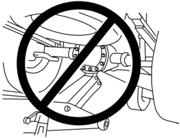
Never use the rear differential as a jacking point.
To lessen the risk of personal injury, do not put any part of your body under the vehicle while changing a tire. Do not start the engine when your vehicle is on the jack. The jack is only meant for changing the tire.
- Remove the lug nuts with the lug wrench.
- Replace the flat tire with the spare tire, making sure the valve stem is facing outward. Reinstall lug nuts until the wheel is snug against the hub. Do not fully tighten the lug nuts until the wheel has been lowered.
If you are using the temporary tire, the lug nut washers will not appear to be flush with the rim. This is normal only when using the temporary spare tire.
- Lower the wheel by turning the jack handle counterclockwise.
186
Roadside Emergencies
-
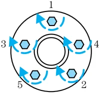
Remove the jack and fully tighten the lug nuts in the order shown. Refer to Wheel lug nut torque specifications later in this chapter for the proper lug nut torque specification.
-
Put flat tire, wheel ornament (if equipped), jack and lug wrench away. Make sure jack is fastened so it does not rattle when you drive.
-
Unblock the wheels.
WHEEL LUG NUT TORQUE SPECIFICATIONS
Retighten the lug nuts to the specified torque at 500 miles (800 km) after any wheel disturbance (tire rotation, changing a flat tire, wheel removal, etc.).
| Bolt size | Wheel lug nut torque* | |
|---|---|---|
| lb.ft. | N•m | |
| 1/2 x 20 | 100 | 135 |
- Torque specifications are for nut and bolt threads free of dirt and rust. Use only Ford recommended replacement fasteners.
⚠ When a wheel is installed, always remove any corrosion, dirt or foreign materials present on the mounting surfaces of the wheel or the surface of the wheel hub, brake drum or brake disc that contacts the wheel. Ensure that any fasteners that attach the rotor to the hub are secured so they do not interfere with the mounting surfaces of the wheel. Installing wheels without correct metal-to-metal contact at the wheel mounting surfaces can cause the wheel nuts to loosen and the wheel to come off while the vehicle is in motion, resulting in loss of control.
JUMP STARTING
⚠ The gases around the battery can explode if exposed to flames, sparks, or lit cigarettes. An explosion could result in injury or vehicle damage.
187
Roadside Emergencies
Batteries contain sulfuric acid which can burn skin, eyes and clothing, if contacted.
Do not attempt to push-start your automatic transmission vehicle. Automatic transmissions do not have push-start capability. Attempting to push-start a vehicle with an automatic transmission may cause transmission damage.
Preparing your vehicle
When the battery is disconnected or a new battery is installed, the automatic transmission must relearn its shift strategy. As a result, the transmission may have firm and/or soft shifts. This operation is considered normal and will not affect function or durability of the transmission. Over time, the adaptive learning process will fully update transmission operation.
- Use only a 12-volt supply to start your vehicle.
- Do not disconnect the battery of the disabled vehicle as this could damage the vehicle's electrical system.
- Park the booster vehicle close to the hood of the disabled vehicle making sure the two vehicles do not touch. Set the parking brake on both vehicles and stay clear of the engine cooling fan and other moving parts.
- Check all battery terminals and remove any excessive corrosion before you attach the battery cables. Ensure that vent caps are tight and level.
- Turn the heater fan on in both vehicles to protect any electrical surges. Turn all other accessories off.
Connecting the jumper cables
188
Roadside Emergencies
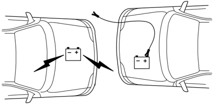
- Connect the positive (+) jumper cable to the positive (+) terminal of the discharged battery.
Note: In the illustrations, lightning bolts are used to designate the assisting (boosting) battery.
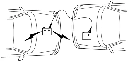
- Connect the other end of the positive (+) cable to the positive (+) terminal of the assisting battery.
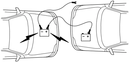
- Connect the negative (-) cable to the negative (-) terminal of the assisting battery.
189
Roadside Emergencies
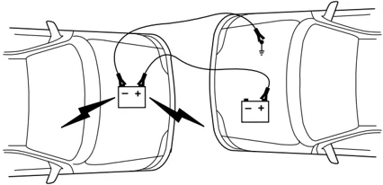
- Make the final connection of the negative (-) cable to an exposed metal part of the stalled vehicle's engine, away from the battery and the carburetor/fuel injection system. Do not use fuel lines, engine rocker covers or the intake manifold as grounding points.
Do not connect the end of the second cable to the negative (-) terminal of the battery to be jumped. A spark may cause an explosion of the gases that surround the battery.
- Ensure that the cables are clear of fan blades, belts, moving parts of both engines, or any fuel delivery system parts.
Jump starting
- Start the engine of the booster vehicle and run the engine at moderately increased speed.
- Start the engine of the disabled vehicle.
- Once the disabled vehicle has been started, run both engines for an additional three minutes before disconnecting the jumper cables.
190
Roadside Emergencies
Removing the jumper cables
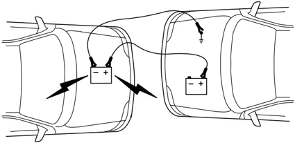
Remove the jumper cables in the reverse order that they were connected.
- Remove the jumper cable from the ground metal surface.
Note: In the illustrations, lightning bolts are used to designate the assisting (boosting) battery.
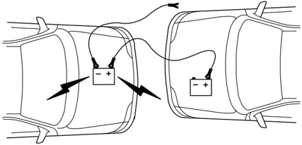
- Remove the jumper cable on the negative (-) connection of the booster vehicle's battery.
191
Roadside Emergencies
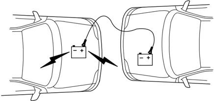
- Remove the jumper cable from the positive (+) terminal of the booster vehicle's battery.
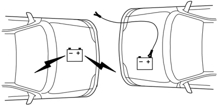
- Remove the jumper cable from the positive (+) terminal of the disabled vehicle's battery.
After the disabled vehicle has been started and the jumper cables removed, allow it to idle for several minutes so the engine computer can relearn its idle conditions.
192
Roadside Emergencies
WRECKER TOWING

If you need to have your vehicle towed, contact a professional towing service or, if you are a member of a roadside assistance program, your roadside assistance service provider.
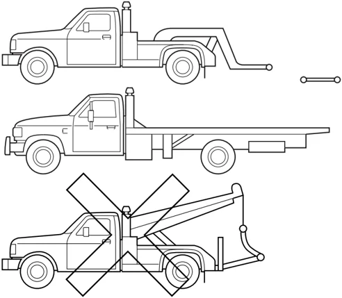
It is recommended that your vehicle be towed with a wheel lift and dollies or flatbed equipment. Do not tow with a slingbelt. Ford Motor Company has not approved a slingbelt towing procedure.
If your vehicle is to be towed from the front using wheel lift equipment, it is recommended that the rear wheels (drive wheels) be placed on a dolly to prevent damage to the transmission.
If the vehicle is towed by other means or incorrectly, vehicle damage may occur.
Ford Motor Company produces a towing manual for all authorized tow truck operators. Have your tow truck operator refer to this manual for proper hook-up and towing procedures for your vehicle.
193