INTERIOR EQUIPMENT
FLOOR MAT
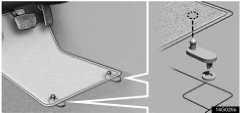
Use a floor mat of the correct size.
If the floor carpet and floor mat have 2 holes, then they are designed for use with locking clips. Fix the floor mat with locking clips into the holes in the floor carpet.
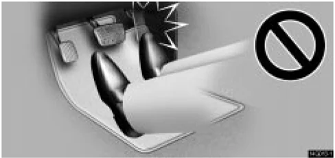
CAUTION Make sure the floor mat is properly placed on the floor carpet. If the floor mat slips and interferes with the movement of the pedals during driving, it may cause an accident.
63
INTERIOR EQUIPMENT
FIRST-AID KIT HOLDER
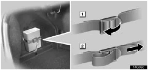
▶ 1 To loosen 2 To tighten This belt is designed to hold the first-aid kit. To loosen: Pull the buckle forward. To tighten: Pull on the belt. Make sure the first-aid kit is securely held.
LUGGAGE STOWAGE PRECAUTIONS
When stowing luggage or cargo in the vehicle, observe the following:
- Put luggage or cargo in the trunk when at all possible. Be sure all items are secured in place.
- Be careful to keep the vehicle level. Placing the weight as far forward as possible helps maintain vehicle balance.
- For better fuel economy, do not carry unnecessary weight.
⚠ CAUTION
- Do not place anything on the package tray behind the rear seatback. Such items may be thrown about and possibly injure people in the vehicle during sudden braking or in an accident.
- Do not drive with objects left on top of the instrument panel. They may interfere with the driver's field of view. Or they may move during sharp vehicle acceleration or turning, and impair the driver's control of the vehicle. In an accident they may injure the vehicle occupants.
NOTICE
Do not load the vehicle beyond the vehicle capacity weight specified on the tire pressure label.
64
SECTION 1 – 5
INSTRUMENTS AND CONTROLS
Exterior equipment
-
Hood . . . . . . . . . . . . . . . . . . . . . . . . . . . . . . . . . . . . . . . . . . . . . . . . . . . . . . . . . . . . . . . . . . . . . . . . . . . . . . . . . . . . . . . . . . . . . . . . . . . . . . . . . . . . . . . . . . . . . . . . . . . . . . . . . . . . . . . . . . . . . . . . . . . . . . . . . . . . . . . . . . . . . . . . . . . . . . . . . . . . . . . . . . . . . . . . . . . . . . . . . . . . . . . . . . . . . . . . . . . . . ........ 66
-
Trunk lid . . . . . . . . . . . . . . . . . . . . . . . . . . . . . . . . . . . . . . . . . . . . . . . . . . . . . . . . . . . . . . . . . . . . . . . . . . . . . . . . . . . . . . . . . . . . . . . . . . . . . . . . . . . . . . . . . . . . . . . . ........ 67
-
Fuel tank cap . . . . . . . . . . . . . . . . . . . . . . . . . . . . . . . . . . . . . . . . . . . . . . . . . . . . . . . . . . . . . . . . . . . . . . . . . . . . . . . . . . . . . . . . . . . . . . . . . . . . . . . . . . . . . . . . . . . . . ........

EXTERIOR EQUIPMENT
HOOD
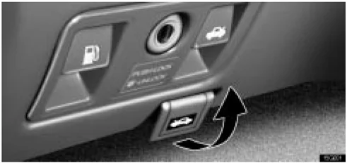
- To open the hood, pull the hood lock release lever under the instrument panel. The hood will spring up slightly.
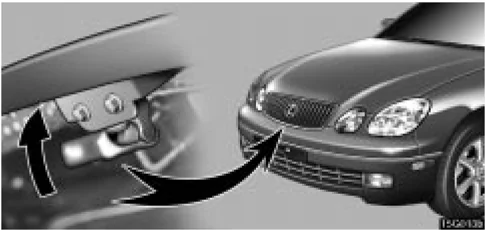
- Insert your fingers under the hood, push up the auxiliary catch lever and lift the hood.
Before closing the hood, check to see that you have not forgotten any tools, rags, etc. Then lower the hood and make sure it locks.
CAUTION
Before driving, be sure that the hood is closed and securely locked. Otherwise, the hood may open unexpectedly while driving and an accident may occur.
66

EXTERIOR EQUIPMENT
TRUNK LID
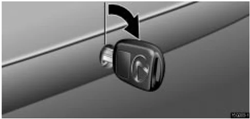
To unlock the trunk lid, insert the master key and turn it clockwise.
To close the trunk lid, lower it and press down on it. After closing the trunk lid, try pulling it up to make sure it is securely closed.
The trunk lid can be unlocked using the wireless remote control key. For details, see page 15.
CAUTION
-
Keep the trunk lid closed while driving. This not only keeps the luggage from being thrown out, but also prevents exhaust gases from entering the vehicle.
-
Always lock the trunk lid and all doors, and keep away the vehicle keys out of children's reach.
-
Never leave children unattended in the vehicle. Unsupervised children may lock themselves in the vehicles or trunk and suffer serious injuries or death.
Trunk lid opener
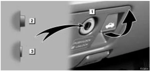
► 1 Main switch 2 Operative 3 Inoperative
To open the trunk lid while sitting in the driver’s seat, pull the lever with the main switch not pushed in.
67
EXTERIOR EQUIPMENT
 1 If you do not want to activate the trunk lid opener system, push in the main switch.
2 To activate the system, insert the master key and turn it counterclockwise.
To protect things put in the trunk, when you have your vehicle parked, push in the main switch.
Internal trunk release handle
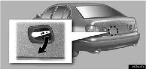
If a person is locked in the trunk, he/she can pull down the phosphorescent handle on the inside of trunk lid to open the trunk lid.
The phosphorescent (glow-in-the-dark) handle will continue to glow for a time after the trunk lid is closed. Exposing the handle to stronger light will cause it to glow longer.
68
EXTERIOR EQUIPMENT
FUEL TANK CAP
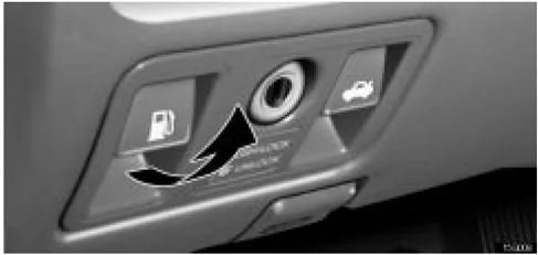
- To open the fuel filler door, pull the lever under the instrument panel.
When refueling, turn off the engine.
CAUTION
- Do not smoke, cause sparks or allow open flames when refuelling. The fumes are flammable.
- When opening the cap, do not remove the cap quickly. In hot weather, fuel under pressure could cause injury by spraying out of the filler neck if the cap is suddenly removed.
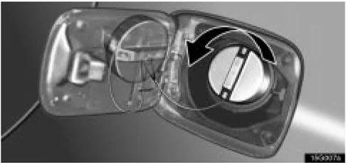
- To remove the fuel tank cap, turn the cap slowly counterclockwise, then pause slightly before removing it. The removed cap can be stored on the back side of the fuel filler door.
It is not unusual to hear a slight swoosh when the cap is opened. When installing the cap, turn the cap clockwise until you hear a click.
If the cap is not installed securely, the malfunction indicator lamp comes on. Make sure the cap is installed securely.
The indicator lamp goes off after driving several times. If the indicator lamp does not go off, contact your Lexus dealer as soon as possible.
69

EXTERIOR EQUIPMENT
CAUTION
- Make sure the cap is installed securely to prevent fuel spillage in the event of an accident.
- Use only a genuine Lexus fuel tank cap for replacement. It is designed to regulate fuel tank pressure.
In case the opener is not actuated
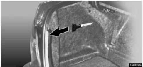
Pull the manual lever toward the back. This is used in case the fuel filler door cannot be opened due to a discharged battery or other trouble.
MOON ROOF
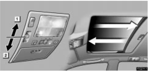
▶ 1 Open 2 Close
To slide open the moon roof, push the switch toward the back. The moon roof will fully open. To stop partway, push the same switch or "TILT" switch.
The sun shade can be opened or closed manually. However, if you open the moon roof, the sun shade will be opened with the moon roof.
To close the moon roof, push the switch toward the front. The moon roof will fully close. To stop partway, push the same switch or "TILT" switch.
70

EXTERIOR EQUIPMENT
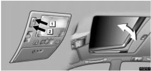
1 Tilt up 2 Lower
To tilt up the rear end of the moon roof fully, push the switch on the rear side or on the front side to lower it.
To operate the moon roof, the ignition key must be in the "ON" position.
Key off operation: Even if the ignition key is turned to the "ACC" or "LOCK" position, the moon roof can be operated until any of the doors is opened (or for about 45 seconds).
Operating the moon roof from outside the vehicle
The moon roof can be closed or opened using an ignition key.* Insert the ignition key into the key hole on the driver's door.
To close the moon roof: Turn the key in the locking direction and hold it.
After the door is locked, the moon roof begins to close. To stop in the middle, return the key.
To open the moon roof: Turn the key in the unlocking direction and hold it.
After the door is unlocked, the moon roof begins to open. To stop in the middle, return the key.
NOTE: *This feature can be set inoperative, or sliding open or tilting up can be selected. Ask your Lexus dealer for details.
71
EXTERIOR EQUIPMENT
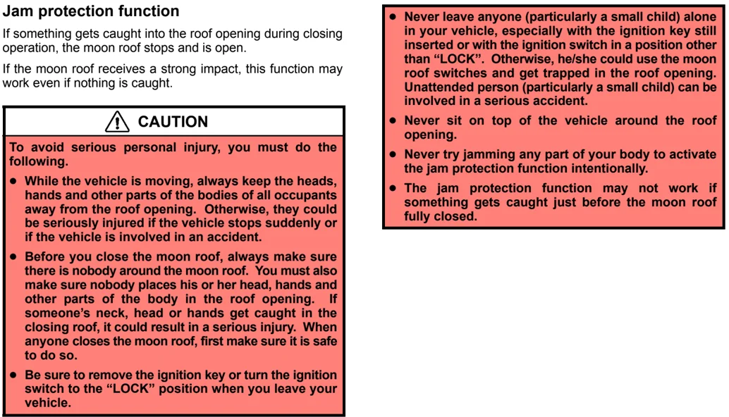
Jam protection function
If something gets caught into the roof opening during closing operation, the moon roof stops and is open.
If the moon roof receives a strong impact, this function may work even if nothing is caught.
CAUTION
To avoid serious personal injury, you must do the following.
-
While the vehicle is moving, always keep the heads, hands and other parts of the bodies of all occupants away from the roof opening. Otherwise, they could be seriously injured if the vehicle stops suddenly or if the vehicle is involved in an accident.
-
Before you close the moon roof, always make sure there is nobody around the moon roof. You must also make sure nobody places his or her head, hands and other parts of the body in the roof opening. If someone's neck, head or hands get caught in the closing roof, it could result in a serious injury. When anyone closes the moon roof, first make sure it is safe to do so.
-
Be sure to remove the ignition key or turn the ignition switch to the "LOCK" position when you leave your vehicle.
-
Never leave anyone (particularly a small child) alone in your vehicle, especially with the ignition key still inserted or with the ignition switch in a position other than "LOCK". Otherwise, he/she could use the moon roof switches and get trapped in the roof opening. Unattended person (particularly a small child) can be involved in a serious accident.
-
Never sit on top of the vehicle around the roof opening.
-
Never try jamming any part of your body to activate the jam protection function intentionally.
-
The jam protection function may not work if something gets caught just before the moon roof fully closed.
72
SECTION 1 – 6
INSTRUMENTS AND CONTROLS
Comfort adjustment
- Seats . . . . . . . . . . . . . . . . . . . . . . . . . . . . . . . . . . . . . . . . . . . . . . . . . . . . . . . . . . . . . . . . . . . . . . . . . . . . . . . . . . . . . . . . . . . . . . . . . . . . . . . . . . . . . . . . . . . . . . . . . . . . . . . . . . . . . . . . . . . . . . . . . . . . . . . . . . . . . . . . . . . . . . . . . . . . . . . . . . . . . . . . . . . . . . . . . . . . . . . . . . . . . . . . . . . . . . . . . . . . ........ 74
- Head restraints . . . . . . . . . . . . . . . . . . . . . . . . . . . . . . . . . . . . . . . . . . . . . . . . . . . . . . . . . . . . . . . . . . . . . . . . . . . . . . . . . . . . . . . . . . . . . . . . . . . . . . . . . . . . . . . . . . . . . ........ 79
- Tilt and telescopic steering wheel . . . . . . . . . . . . . . . . . . . . . . . . . . . . . . . . . . . . . . . . . . . . . . . . . . . . . . . . . . . . . . . . . . . . . . . . . . . . . . . . . . . . . . . . . . . . . . . . . . . . . . . . . . . . . ........

COMFORT ADJUSTMENT
SEATS
While the vehicle is being driven, all vehicle occupants should have the seatback upright, sit well back in the seat and properly wear the seat belts provided.
CAUTION
- Do not drive the vehicle unless the occupants are properly seated. Do not allow passengers to sit in the luggage compartment or cargo area. Persons not properly seated and/or properly restrained by seat belts can be severely injured in the event of emergency braking or a collision.
- During driving, do not allow passengers to stand up or move around between seats. Otherwise, severe injuries can occur in the event of emergency braking or a collision.
Front seat precautions
Driver seat
CAUTION
The driver airbag deploys with considerable force, and can cause death or serious injury especially if the driver is very close to the airbag. The National Highway Traffic Safety Administration ("NHTSA") advises:
Since the risk zone for driver airbag is the first 50–75 mm (2–3 in.) of inflation, placing yourself 250 mm (10 in.) from your driver airbag provides you with a clear margin of safety. This distance is measured from the center of the steering wheel to your breastbone. If you sit less than 250 mm (10 in.) away now, you can change your driving position in several ways:
- Move your seat to the rear as far as you can while still reaching the pedals comfortably.
- Slightly recline the back of the seat. Although vehicle designs vary, many drivers can achieve the 250 mm (10 in.) distance, even with the driver seat all the way forward, simply by reclining the back of the seat somewhat. If reclining the back of your seat makes it hard to see the road, raise yourself by using a firm, non-slippery cushion, or raise the seat if your vehicle has that feature.
74
COMFORT ADJUSTMENT
- If your steering wheel is adjustable, tilt it downward. This points the airbag toward your chest instead of your head and neck.
The seat should be adjusted as recommended by NHTSA above, while still maintaining control of the foot pedals, steering wheel, and your view of the instrument panel controls.
Front passenger seat
CAUTION
The front passenger airbag also deploys with considerable force, and can cause death or serious injury especially if the front passenger is very close to the airbag. The front passenger seat should be as far from the airbag as possible with the seatback adjusted, so the front passenger sits upright.
Front seats
CAUTION
The side airbags are installed in the driver and front passenger seats. Observe the following precautions.
- Do not lean against the front door when the vehicle is in use, since the side airbag inflates with considerable speed and force. Otherwise, you may be killed or severely injured.
- Do not use seat accessories which cover the parts where the side airbags inflate. Such accessories may prevent the side airbags from activating correctly, causing death or serious injury.
- Do not modify or replace the seats or upholstery of front seats equipped with side airbags. Such changes may prevent the side airbags from activating correctly, disable the system, or cause the side airbags to inflate accidentally, resulting in death or serious injury.
75
COMFORT ADJUSTMENT
Seat adjustment precautions
CAUTION
- Do not adjust the seat while the vehicle is moving as the seat may unexpectedly move and cause the driver to lose control of the vehicle.
- Be careful that the seat does not hit a passenger, luggage, or the rear seat.
NOTICE Do not operate the control switch in more than one dimension at a time. It may cause electrical overload.
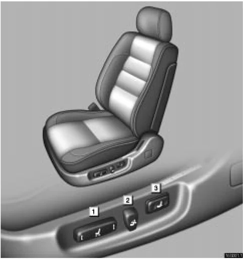
Adjusting front seats

1 Seat position control switch, seat cushion angle and height control switch 2 Seatback angle control switch 3 Lumbar support control switch
76
COMFORT ADJUSTMENT
Adjusting seat position
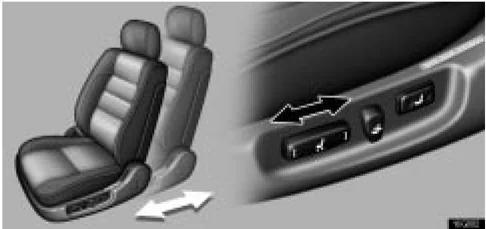
Move the control switch in the desired direction. Releasing the switch will stop the seat in that position. Do not place anything under the seat, as this might interfere with the seat movement.
Adjusting seatback angle
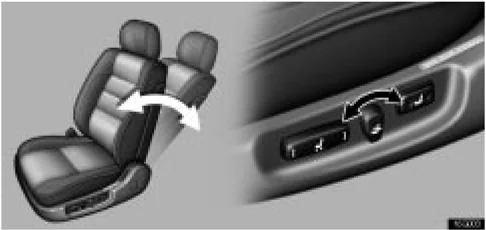
Move the control switch in the desired direction. Releasing the switch will stop the seatback in that position.
⚠ CAUTION To reduce the risk of sliding under the lap belt during a collision, avoid reclining the seatback any more than needed. The seat belts provide maximum protection in a frontal or rear collision when the driver and the passenger are sitting up straight and well back in the seats. If you are reclined, the lap belt may slide past your hips and apply restraint forces directly to the abdomen. In the event of a frontal collision, the more the seat is reclined, the greater the risk of personal injury.
77
COMFORT ADJUSTMENT
Adjusting seat cushion angle and height
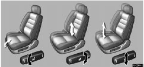
Move the control switch in the desired direction. Releasing the switch will stop the seat cushion in that position.
Adjusting lumbar support
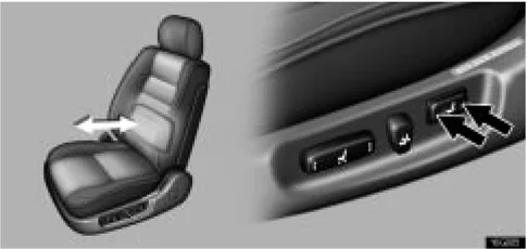
Push the control switch on either side. The amount of lumbar support will change while the switch is pushed.
78
COMFORT ADJUSTMENT
HEAD RESTRAINTS
Front seats
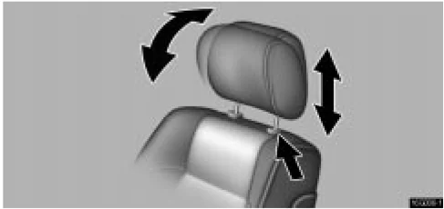
To raise the head restraint, pull it up. To lower it, press the lock release button and push the head restraint down. To move the head restraint forward or rearward, pull or push on the top.
The head restraint is most effective when it is close to your head. Therefore, using a cushion on the seatback is not recommended.
CAUTION
- Adjust the center of the head restraint so that it is closest to the top of your ears.
- After adjusting the head restraint, make sure it is locked in position.
- Do not drive with the head restraints removed.
Rear seats
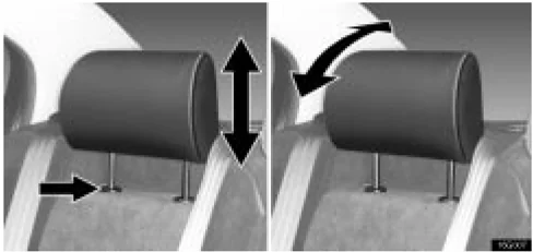
▶Outside rear seats
To raise the head restraint, pull it up. To lower it, press the lock release button and push the head restraint down. To move the head restraint forward or rearward, pull or push on the top.
79

COMFORT ADJUSTMENT
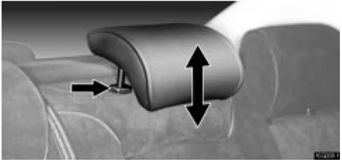
▶Center rear seat
To raise the head restraint, pull it up. To lower it, press the lock release button and push the head restraint down.
Center rear head restraint: When an occupant sits on the center rear seat, always pull up the head restraint to the lock position.
The head restraint is most effective when it is close to your head. Therefore, using a cushion on the seatback is not recommended.
CAUTION
- Adjust the center of the head restraint so that it is closest to the top of your ears.
- After adjusting the head restraint, make sure it is locked in position.
- Do not drive with the head restraints removed.
TILT AND TELESCOPIC STEERING WHEEL
Adjustment of steering wheel tilt
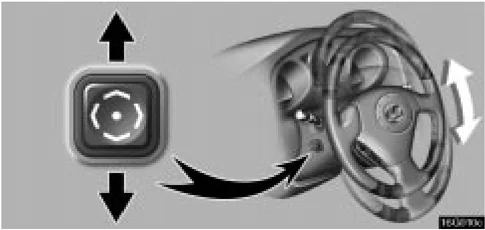
To adjust the tilt of the steering wheel, push the control switch upward or downward to set it to the desired position.
CAUTION Do not adjust the steering wheel while the vehicle is moving. Doing so may cause the driver to mishandle the vehicle and an accident may occur resulting in death or serious injuries.
80
COMFORT ADJUSTMENT
Adjustment of telescopic steering column
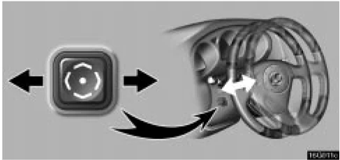
To adjust the steering column length, push the control switch forward or backward to set the steering wheel to the desired position.
CAUTION Do not adjust the steering column while the vehicle is moving. Doing so may cause the driver to mishandle the vehicle and an accident may occur resulting in death or serious injuries.
Auto tilt away*
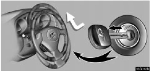
When the ignition key is removed, the steering column moves forward away from the driver and also tilts up for easy exit and entry.
When the key is inserted in the ignition switch, the steering column returns to the previously set position.
NOTE: This feature can be deactivated. Ask your Lexus dealer for details.
81
COMFORT ADJUSTMENT
OUTSIDE REAR VIEW MIRRORS
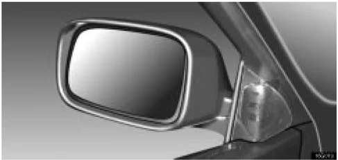
Adjust the mirror so that you can just see the side of your vehicle in the mirror.
Be careful when judging the size or distance of any object seen in the outside rear view mirror on the passenger's side because it is a convex mirror. Any object seen in a convex mirror will look smaller and farther away than if seen in a normal flat mirror.
When the inside rear view mirror darkens in "AUTO" mode, the outside rear view mirrors also darken to reduce the reflection of the headlights of the following vehicle. For details, see "Inside rear view mirror" on page 83.
When you push the rear window defogger switch, the heater panels in the outside rear view mirrors will quickly clear the mirror surface. (See "Rear window and outside rear view mirror defogger switch" on page 31.)
CAUTION
- Do not adjust the mirror while the vehicle is moving. Doing so may cause the driver to mishandle the vehicle and an accident may occur resulting in death or serious injuries.
- Since the mirror surfaces can get hot, do not touch them when the rear window and outside rear view mirror defogger switch is on.
Power rear view mirror control

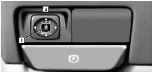
1 Master switch 2 Control switch
To adjust the power rear view mirror, first place the master switch at "L" (left) or "R" (right), and push the control switch on the desired side.
The power rear view mirrors can be adjusted when the key is in the "ACC" or "ON" position.
82
COMFORT ADJUSTMENT
NOTICE If ice should jam the mirror, do not operate the control or scrape the mirror face. Use a spray de-icer to free the mirror.
Folding rear view mirrors
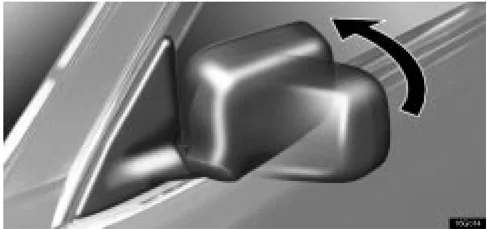
To fold the rear view mirror, push backward.
The rear view mirrors can be folded backward for parking in compact areas.
CAUTION Do not drive with the mirrors folded backward. Both the driver and passenger side rear view mirrors must be extended and properly adjusted before driving.
INSIDE REAR VIEW MIRROR
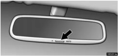
Adjust the mirror so that you can just see the rear of your vehicle in the mirror.
Pushing the switch changes the mode between "AUTO" and "DAY".
The indicator comes on when the "AUTO" mode is selected.
"DAY" mode: The mirror surface is normal.
"AUTO" mode: If the mirror detects light from the headlights of the vehicle behind you, the mirror surface darkens slightly to reduce the reflected light.
When the inside rear view mirror surface changes, the outside rear view mirror surfaces will also become darker.
When the ignition key is inserted and turned on, the inside rear view mirror always turns on in the "AUTO" mode.
83
COMFORT ADJUSTMENT
When the outside air temperature is low, it may take a little longer for the mirror to darken in response to the detection of headlights.
CAUTION
Do not adjust the mirror while the vehicle is moving. Doing so may cause the driver to mishandle the vehicle and an accident may occur resulting in death or serious injuries.

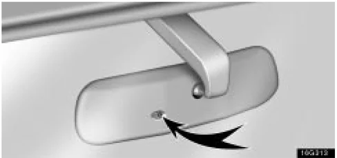
To ensure correct functioning of an anti-glare mirror sensor located on the back side of the mirror, do not touch or cover the sensor with your finger or a piece of cloth, etc.
Compass (Vehicles without Navigation System sold in U.S. mainland and Canada)
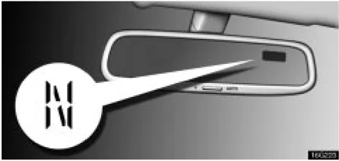
The compass indicates the direction in which the vehicle is heading. The illustration shown above indicates the vehicle is heading north.
| Displays | Directions |
|---|---|
| N | North |
| NE | Northeast |
| E | East |
| SE | Southeast |
| S | South |
| SW | Southwest |
| W | West |
| NW | Northwest |
COMFORT ADJUSTMENT
Pushing the button for longer than 3 seconds turns on or off the compass display.
The compass may not show the correct direction in the following conditions:
- The vehicle is stopped immediately after turning. The compass does not adjust while the vehicle is stopped.
- The ignition switch is turned off immediately after turning.
- The vehicle is on an inclined surface.
- The vehicle is in a place where the earth’s magnetic field is subject to interference by artificial magnetic fields (underground parking, under a steel tower, between buildings, roof parking, near a crossing, near a large vehicle, etc.).
- The vehicle is magnetized. (There is a magnet or a metal object near the inside rear view mirror.)
- The battery has been disconnected.
- Any door is open.
The compass works to calibrate the direction automatically while the vehicle in in motion, if deviation is small.
For obtaining additional precision or for complete calibrating, see “CALIBRATING THE COMPASS” below.
NOTICE Do not put magnets or a metal object near the inside rear view mirror. Doing this may cause malfunction of the compass sensor.
CALIBRATING THE COMPASS (deviation calibration)
The direction display on the compass deviates from the true direction determined by the earth’s magnetic field. The amount of deviation varies according to the geographic position of the vehicle.
To adjust for this deviation, stop the vehicle and push the button for longer than about 6 seconds until the number (1–15) appears on the display. Then push the button again, referring to the following map to select the number of the zone where the vehicle is.
85
COMFORT ADJUSTMENT
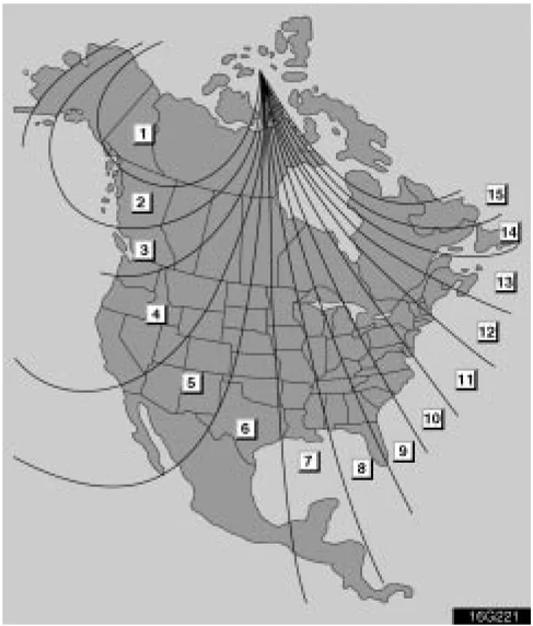
►Zone number If the direction is displayed several seconds after adjustment, the calibration is finished.
CAUTION Do not adjust the display while the vehicle is moving. Be sure to adjust the display only when the vehicle is stopped.
CALIBRATING THE COMPASS (circling calibration)
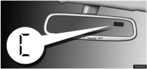
“C” appears on the display in case the circling calibration is required due to a drastic change in the magnetic field. To rectify this, follow the calibration procedure below.
86
COMFORT ADJUSTMENT
 TMA3229
Drive the vehicle slowly (at 8 km/h (5 mph) or lower) in a circle until the direction is displayed. If there is not enough space to drive in a circle, drive around the block until the direction is displayed.
After driving in 1 to 3 circles in the above method, calibration is complete with the direction shown on the display.
If calibration cannot be performed because of the vehicle is magnetized, take your vehicle to a Lexus dealer.
- Do not perform circling calibration of the compass in a place where the earth's magnetic field is subject to interference by artificial magnetic fields (underground parking, under a steel tower, between buildings, roof parking, near a crossing, near a large vehicle, etc.).
- During calibration, do not operate electric systems (moon roof, power windows, etc.) as they may interfere with the calibration.
CAUTION
- When doing the circling calibration, be sure to secure a wide space, and watch out for people and vehicles in the neighborhood. Do not violate any local traffic rules while performing circling calibration.
- Do not adjust the display while the vehicle is moving. Be sure to adjust the display only when the vehicle is stopped.
87