Practical hints
Where will I find ...?
▼ Where will I find ...?
First aid kit
The first aid kit is located in the trunk on the left side secured by a hook and loop fastener.
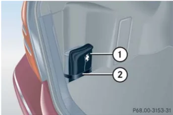
① First aid kit ② Hook and loop fastener
► Unfasten hook and loop fastener ②. ► Remove first aid kit ①.
Check expiration dates and contents for completeness at least once a year and replace missing/expired items.
Vehicle tool kit
The vehicle tool kit is located in the storage compartment underneath the trunk floor.
The following is included:
- Towing eye bolt
- Wheel wrench
- Alignment bolt
- Vehicle jack
- Spare wheel bolts
- Spare fuses
- Collapsible wheel chock
- A pair of gloves
Removing the vehicle tool kit
► Lift up trunk floor cover and engage trunk floor handle in upper edge of trunk.
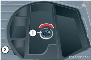
① Retaining screw ② Storage well casing
► Loosen retaining screw ① by turning it counterclockwise. ► Remove storage well casing ②. >>
377
Practical hints
Where will I find ...?
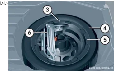
③ Arrow ④ Minispare wheel ⑤ Vehicle tool kit storage well casing ⑥ Vehicle tool kit
▶ Remove vehicle tool kit ⑥.
Storing the vehicle tool kit
▶ Place vehicle tool kit ⑥ in vehicle tool kit storage well casing ⑤.
▶ Place storage well casing ② over the vehicle tool kit storage well casing ⑤ and turn retaining screw ① clockwise as far it will go to secure the Minispare wheel.
Arrow ③ on vehicle tool kit storage well casing ⑤ must point in the direction of travel. Otherwise you cannot place the storage well casing ② on top and secure the Minispare wheel with retaining screw ①.
To prevent damage, always disengage trunk floor handle from upper edge of trunk and lower trunk floor before closing the trunk lid.
378
Practical hints
Where will I find ...?
Vehicle jack
Warning!
The jack is designed exclusively for jacking up the vehicle at the jack take-up brackets built into both sides of the vehicle. To help avoid personal injury, use the jack only to lift the vehicle during a wheel change. Never get beneath the vehicle while it is supported by the jack. Keep hands and feet away from the area under the lifted vehicle. Always firmly set parking brake and block wheels before raising vehicle with jack.
Do not disengage parking brake while the vehicle is raised. Be certain that the jack is always vertical (plumb line) when in use, especially on hills. Always try to use the jack on level surface. Make sure the jack arm is fully seated in the jack take-up bracket. Always lower the vehicle onto sufficient capacity jackstands before working under the vehicle.
The vehicle jack is located in the storage compartment underneath the trunk floor.
 P40.10-2773-31
Storage position
► Remove vehicle jack from its compartment.
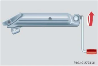
► Push crank handle up.
 P40.10-2774-31
Operational position
► Turn crank handle clockwise until it engages (operational position).
Before storing the vehicle jack in its compartment:
• It should be fully collapsed.
• The handle must be folded in (storage position).
379
Practical hints
Where will I find ...?
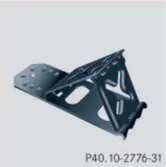
Setting up the collapsible wheel chock
The collapsible wheel chock serves to additionally secure the vehicle, e.g. while changing the wheel.
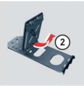
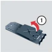
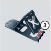
① Tilt the plate upward ② Fold the lower plate outward ③ Insert the plate
P40.10-2776-31
► Tilt both plates upward ①. ► Fold the lower plate outward ②. ► Guide the tabs of the lower plate all the way into the openings of the base plate ③.
Minispare wheel
The Minispare wheel is located in the storage compartment underneath the trunk floor.
Removing the Minispare wheel
► Lift up trunk floor cover and engage trunk floor handle in upper edge of trunk. ► Loosen the retaining screw (▷ page 377) in the middle of storage well casing. ► Remove the storage well casing (▷ page 377).
380
Practical hints
Where will I find ...?
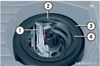
① Vehicle tool kit ② Arrow ③ Minispare wheel ④ Vehicle tool kit storage well casing
▶ Remove vehicle tool kit storage well casing ④.
▶ Remove Minispare wheel ③.
Storing the Minispare wheel
▶ Place Minispare wheel ③ in wheel well.
▶ Place vehicle tool kit storage well casing ④ over the Minispare wheel. Make sure arrow ② on vehicle tool kit storage well casing ④ points in the direction of travel.
▶ Place storage well casing (▷ page 377) over vehicle tool kit storage well casing ④ and turn the retaining screw (▷ page 377) clockwise as far it will go to secure the Minispare wheel.
i Arrow ② on vehicle tool kit storage well casing ④ must point in the direction of travel. Otherwise you cannot place the storage well casing (▷ page 377) on top and secure the Minispare wheel with the retaining screw (▷ page 377).
! To prevent damage, always disengage trunk floor handle from upper edge of trunk and lower trunk floor before closing the trunk lid.
Warning!
The dimensions of the Minispare wheel are different from those of the road wheels. As a result, the vehicle handling characteristics change when driving with a Minispare wheel mounted.
The Minispare wheel should only be used temporarily, and should be replaced with a regular road wheel as quickly as possible.
381
Practical hints
Where will I find ...?
In the case of a flat tire, you may temporarily use the Minispare wheel when observing the following restrictions:
- Do not exceed a vehicle speed of 50 mph (80 km/h).
- Drive to the nearest tire repair facility to have the flat tire repaired or replaced as appropriate.
- Do not operate vehicle with more than one Minispare wheel mounted.
For more information, see “Rims and Tires” (> page 424).
Spare wheel bolts
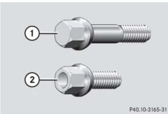
① Wheel bolt for light alloy rims ② Wheel bolt for Minispare wheel or other steel rims (located in trunk with spare wheel)
! Wheel bolts ② must be used when mounting the Minispare wheel or other steel rims. The use of any wheel bolts other than wheel bolts ② for the Minispare wheel or other steel rims will physically damage the vehicle’s brakes.
Warning! Make sure to use the original length wheel bolts when remounting the original wheel after it has been repaired.
382
Practical hints
Unlocking/locking in an emergency
▼ Unlocking/locking in an emergency
Unlocking the vehicle
If you are unable to unlock the vehicle with the SmartKey, open the driver’s door and the trunk using the mechanical key.
(i) Unlocking the driver’s door and/or the trunk with the mechanical key will trigger the anti-theft alarm system*.
To cancel the alarm, do one of the following:
- Press button or on the SmartKey.
- Insert the SmartKey in the starter switch.
Removing the mechanical key
P80.20-2390-31
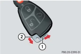
① Mechanical key locking tab ② Mechanical key
▶ Move locking tab ① in direction of arrow.
▶ Slide mechanical key ② out of the housing.
Unlocking the driver's door
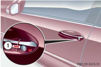
P80.20-2615-31
① Unlocking
▶ Insert the mechanical key into the driver's door lock until it stops.
▶ Turn the mechanical key counterclockwise to position ①.
The driver's door is unlocked.
383
Practical hints
Unlocking/locking in an emergency
Unlocking and opening the trunk
A minimum height clearance of 5.71 ft (1.74 m) is required to open the trunk lid.
The trunk lid lock is located next to the handle above the rear license plate recess.
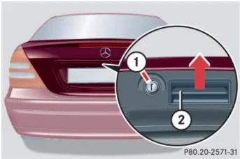
① Unlocking in an emergency ② Handle
► Insert the mechanical key into the trunk lid lock until it stops.
► Turn the mechanical key counterclockwise to position ①. The trunk lid unlocks.
► Pull on handle ②. The trunk lid opens.
! The trunk lid swings open upwards automatically. Always make sure there is sufficient overhead clearance.
► Turn the mechanical key back and remove it from the trunk lid lock.
Locking the vehicle
If you are unable to lock the vehicle with the SmartKey, do the following:
► Close the passenger doors and the trunk lid.
► Press the central locking switch in the center console (▷ page 104).
► Check to see whether the locking knobs on the passenger doors have moved down.
► If necessary push them down manually. Except for the driver's door, the vehicle should now be locked.
Practical hints
Unlocking/locking in an emergency
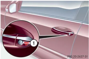
① Locking ► Insert the mechanical key into the driver’s door lock until it stops. ► Turn the mechanical key clockwise to position ①. The driver’s door is locked.
Fuel filler flap
In case the central locking system does not release the fuel filler flap, you can open it manually.
Warning! If you operate the emergency release button, be careful of the sharp edges so that you do not injure yourself.
The release button is on the right-hand side of the luggage compartment behind the side trim.
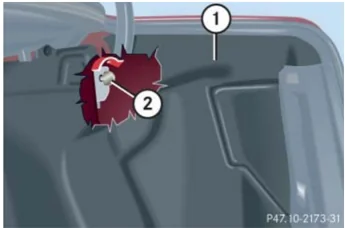
① Side trim ② Release button ► Open the trunk lid. ► Remove the side trim ① from the right-hand side of the luggage compartment. ► Turn release button ② clockwise as far as will go. The fuel filler flap is released. ► Open the fuel filler flap from outside.
385
Practical hints
Unlocking/locking in an emergency
Manually unlocking the transmission gear selector lever
In the case of power failure the transmission gear selector lever can be manually unlocked, e.g. to tow the vehicle.
► Slide out the swiveling cup holder (▷ page 261).
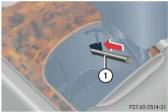
① Tool
► Insert a tool ① (e.g. flat blade screwdriver) into the opening.
► Perform the following two steps simultaneously:
► Press tool ① forward in the direction of the arrow.
► Move gear selector lever from position P.
► Remove tool ① from the opening.
The gear selector lever is locked again when moving it to position P.
386
Practical hints
Opening/closing in an emergency
▼ Opening/closing in an emergency
Power tilt/sliding sunroof*
You can open or close the tilt/sliding sunroof manually should an electrical malfunction occur.
The tilt/sliding sunroof drive is located behind the lens ① of the interior overhead light.
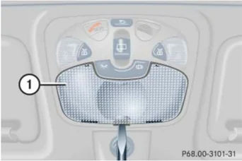
P68.00-3101-31
► Remove SmartKey from the starter switch.
► Pry of lens ① using a flat blade screwdriver.
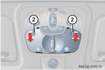
P68.00-3102-31
► Slide both locking tabs ② in direction of the arrows.
► Lower the rear of the cover and remove.
► Remove the cover.
► Take the crank ③ out of the Operator's Manual pouch.
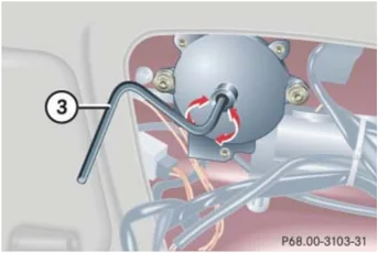
Do not disconnect electrical connectors.
► Insert crank ③ through hole on the left side.

P68.00-3103-31
► Turn crank ③ clockwise to:
- slide sunroof closed
- raise sunroof at the rear
► Turn crank ③ counterclockwise to:
- slide sunroof open
- lower sunroof at the rear

Turn crank ③ slowly and smoothly. The tilt/sliding sunroof must be synchronized after being operated manually (▷ page 248).
387
Practical hints
Replacing SmartKey batteries
If the batteries in the SmartKey are discharged, the vehicle can no longer be locked or unlocked. It is recommended to have the batteries replaced at an authorized Mercedes-Benz Center.
Warning! Keep the batteries out of reach of children. If a battery is swallowed, seek medical help immediately.
Batteries contain materials that can harm the environment if disposed of improperly. Recycling of batteries is the preferred method of disposal. Many states require sellers of batteries to accept old batteries for recycling.
- When inserting the batteries, make sure they are clean and free of lint.
- When replacing batteries, always replace both batteries.
The required replacement batteries are available at any Mercedes-Benz Center.
388
SmartKey
Replacement batteries: Lithium, type CR 2025 or equivalent.
► Remove the mechanical key (▷ page 383).
 P80.35-2191-31
① Mechanical key ② Battery compartment
► Insert mechanical key ① in side opening and push grey slide. Battery compartment ② is unlatched.
► Pull battery compartment ② out of the housing in direction of arrow.
► Remove the batteries.
 P80.35-2107-31
③ Battery ④ Contact spring
Practical hints
Replacing SmartKey batteries
► Using a lint-free cloth, insert new batteries ③ under contact spring ④ with the plus (+) side facing up.
► Return battery compartment ② into housing until it locks into place.
► Slide mechanical key ① back into the SmartKey.
► Check the operation of the SmartKey.
389
Practical hints
Replacing bulbs
Safe vehicle operation depends on proper exterior lighting and signaling. It is therefore essential that all bulbs and lamp assemblies are in good working order at all times.
Correct headlamp adjustment is extremely important. Have headlamps checked and readjusted at regular intervals and when a bulb has been replaced. See an authorized Mercedes-Benz Center for headlamp adjustment.
If the headlamps or front fog lamps are fogged up on the inside as a result of high humidity, driving the vehicle a distance with the lights on should clear up the fogging.
Substitute bulbs will be brought into use when lamps malfunction. Observe the messages in the multifunction display (▷ page 371).
Bulbs
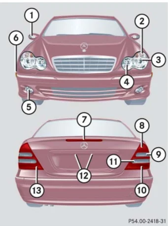
P54.00-2418-31
390
Practical hints
Replacing bulbs
Front lamps
| Lamp | Type |
|---|---|
| ① Additional turn signal lamp | LED |
| ② Halogen headlamp: Turn signal lampBi-Xenon* headlamp: Turn signal lamp | 1156 A2357 A |
| ③ Halogen headlamp: Low beamBi-Xenon* headlamp: Low and high beam¹ | H7 (55 W)D2S-35 W |
¹ Vehicles with Bi-Xenon* headlamps: Low beam and high beam use the same D2S-35W lamp. Do not replace the Xenon bulbs yourself. See an authorized Mercedes-Benz Center.
Rear lamps
| Lamp | Type |
|---|---|
| ⑦ High mounted brake lamp | LED |
| ⑧ Brake lamp | P 21 W |
| ⑨ Turn signal lamp | PY 21 W |
| ⑩ Parking and side marker lamp | P 21/5 W |
| ⑪ Backup lamp | P 21 W |
| ⑫ License plate lamps | C 5 W |
| ⑬ Rear fog lamp (driver’s side only), tail and standing lamp | P 21/4 W |

391
Practical hints
Replacing bulbs
Warning!
Bulbs and bulb sockets can be very hot. Allow the lamp to cool down before changing a bulb.
Keep bulbs out of reach of children.
Halogen lamps contain pressurized gas. A bulb can explode if you
- touch or move it when hot
- drop the bulb
- scratch the bulb
Wear eye and hand protection.
Because of high voltage in Xenon lamps, it is dangerous to replace the bulb or repair the lamp and its components. We recommend that you have such work done by a qualified technician.
Notes on bulb replacement
- Only use 12 volt bulbs of the same type and with the specified watt rating.
- Switch lights off before changing a bulb to prevent short circuits.
- Always use a clean lint-free cloth when handling bulbs.
- Your hands should be dry and free of oil and grease.
- If the newly installed bulb does not come on, visit an authorized Mercedes-Benz Center.
Have the LEDs and bulbs for the following lamps replaced by an authorized Mercedes-Benz Center:
- Additional turn signals in the exterior rear view mirrors
- High mounted brake lamp
- Xenon* lamps
- Front fog lamps
Have the headlamp adjustment checked regularly.
392
Practical hints
Replacing bulbs
Replacing bulbs for front lamps
Before you start to replace a bulb for a front lamp, do the following first:
► Turn the exterior lamp switch to position 0 (▷ page 117).
► Open the hood (▷ page 296) (except for side marker lamps).
Halogen headlamp
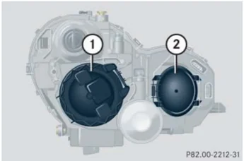
① Housing cover for low beam headlamp ② Housing cover for high beam headlamp, parking and standing lamp
P82.00-2212-31
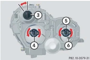
P82.10-3579-31
③ Bulb socket for turn signal lamp bulb ④ Bulb socket for low beam bulb ⑤ Bulb socket for high beam bulb ⑥ Bulb socket for parking and standing lamp bulb
Low beam bulb
► Press the clamp on housing cover ① and remove it.
► Pull the electrical connector off.
► Turn bulb socket ④ counterclockwise and take out the bulb.
► Insert the new bulb so that its socket locates in the recess of the lamp housing.
► Turn bulb socket ④ clockwise until it engages.
► Plug the electrical connector onto the bulb.
► Align housing cover ① and press until it engages.
393
Practical hints
Replacing bulbs
High beam bulb
- Press the clamp on housing cover ② and remove it.
- Pull the electrical connector off.
- Turn bulb socket ⑤ counterclockwise and take out the bulb.
- Insert the new bulb so that its socket locates in the recess of the lamp housing.
- Turn bulb socket ⑤ clockwise until it engages.
- Plug the electrical connector onto the bulb.
- Align housing cover ② and press until it engages.
Front turn signal lamp bulb
- Turn bulb socket ③ with the bulb counterclockwise and remove it.
- Press gently onto the bulb and turn it counterclockwise out of bulb socket ③.
- Press new bulb gently into bulb socket ③ and turn clockwise until it engages.
- Place bulb socket ③ back into the lamp and turn it clockwise.
Parking and standing lamp bulb
- Press the clamp on housing cover ② and remove it.
- Pull out bulb socket ⑥ with the bulb.
- Pull the bulb out of bulb socket ⑥.
- Press the new bulb into bulb socket ⑥.
- Press bulb socket ⑥ back into the lamp.
- Align housing cover ② and press until it engages.
394
Practical hints
Replacing bulbs
Bi-Xenon* headlamp
Warning!
Do not remove the cover ① for the Bi-Xenon headlamp. Because of high voltage in Bi-Xenon lamps, it is dangerous to replace the bulb or repair the lamp and its components. We recommend that you have such work done by a qualified technician.

P82.30-2332-31
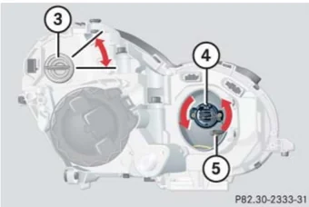
① Housing cover for Bi-Xenon headlamp ② Housing cover for high beam flasher, parking and standing lamp
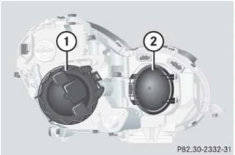
P82.30-2333-31
③ Bulb socket for turn signal lamp bulb ④ Bulb socket for high beam flasher bulb ⑤ Bulb socket for parking and standing lamp bulb
High beam flasher bulb
▶ Press the clamp on housing cover ② and remove it.
▶ Pull the electrical connector off.
▶ Turn bulb socket ④ counterclockwise and take out the bulb.
▶ Insert the new bulb so that its socket locates in the recess of the lamp housing.
▶ Turn bulb socket ④ clockwise until it engages.
▶ Plug the electrical connector onto the bulb.
▶ Align housing cover ② and press until it engages.
395
Practical hints
Replacing bulbs
Front turn signal lamp bulb
- Turn bulb socket ③ with the bulb counterclockwise and remove it.
- Press gently onto the bulb and turn it counterclockwise out of bulb socket ③.
- Press new bulb gently into bulb socket ③ and turn clockwise until it engages.
- Place bulb socket ③ back into the lamp and turn it clockwise.
Parking and standing lamp bulb
- Press the clamp on housing cover ② and remove it.
- Pull out bulb socket ⑤ with the bulb.
- Pull the bulb out of bulb socket ⑤.
- Press the new bulb into bulb socket ⑤.
- Press bulb socket ⑤ back into the lamp.
- Align housing cover ② and press until it engages.
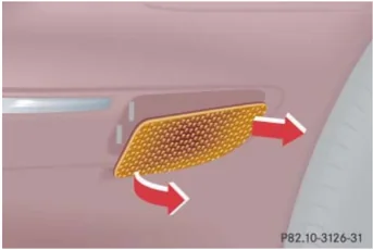
Side marker lamp
P82.10-3126-31
- Carefully slide the lamp towards the rear in direction of arrows.
- Remove the front end first.
- Turn the bulb socket with the bulb counterclockwise and remove it.
- Pull the bulb out of the bulb socket.
- Insert the new bulb into the bulb socket.
- Place the bulb socket back into the lamp and turn it clockwise.
- To reinstall the lamp, set the rear end in the bumper and let the front end engage.
396
Practical hints
Replacing bulbs
Replacing bulbs for rear lamps
Before you start to replace a bulb for a rear lamp, do the following first:
- Turn the exterior lamp switch to position 0 (▷ page 117).
- Open the trunk lid (▷ page 99).
Tail lamp unit
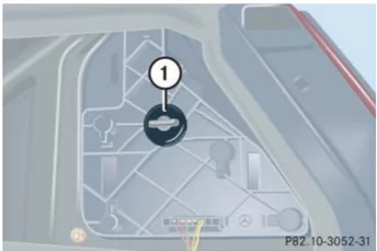
① Latch
- Fold the corresponding trim panel to the side.
- Turn latch ① to vertical position and remove the bulb carrier.
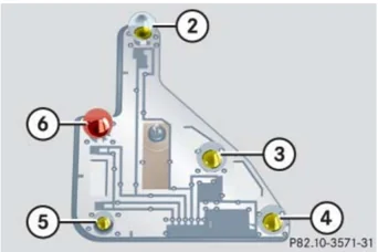
Bulb carrier
② Brake lamp bulb ③ Backup lamp bulb ④ Rear fog lamp (driver's side only), tail and standing lamp bulb ⑤ Parking and side marker lamp bulb ⑥ Turn signal lamp bulb
- Press gently onto the respective bulb and turn counterclockwise out of its bulb socket.
- Press the new bulb gently into its bulb socket and turn clockwise until it engages.
- Reinstall the bulb carrier and lock it again with latch ①.
- Reinstall the trim panel.
License plate lamp
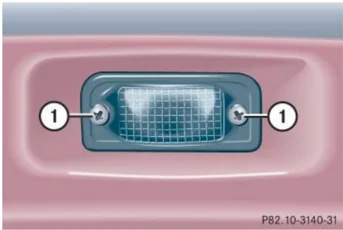
① Screw
- Loosen both screws ①.
- Remove the license plate lamp.
- Replace the bulb.
- Reinstall the license plate lamp.
- Retighten screws ①.
397
Practical hints
Replacing wiper blades
Removing wiper blades
Warning! For safety reasons, switch off wipers and remove SmartKey from starter switch before replacing a wiper blade. Otherwise, the wiper motor could suddenly turn on and cause injury.
► Remove SmartKey from starter switch. ► Fold wiper arm forward.

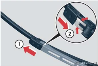
① Unlock ② Lock
► Pull the tab in direction of arrow ① and remove wiper blade.
Installing wiper blades
► Slide the wiper blade into the cutout on the wiper arm (see arrows). ► Slide the tab back in the direction of arrow ② until it audibly engages. ► Fold the wiper arm backward to rest on the windshield. Make sure you hold on to the wiper when folding the wiper arm back.
! Never open the hood when the wiper arms are folded forward.
Hold on to the wiper when folding the wiper arm back. If released, the force of the impact from the tensioning spring could crack the windshield.
Do not allow the wiper arms to contact the windshield glass without a wiper blade inserted.
Make certain that the wiper blades are properly installed. Improperly installed wiper blades may cause windshield damage.
For your convenience, we recommend that you have this work carried out by an authorized Mercedes-Benz Center.
398