Operation
Tires and wheels
See an authorized Mercedes-Benz Center for information on tested and recommended rims and tires for summer and winter operation. They can also offer advice concerning tire service and purchase.
Warning! Replace rims or tires with the same designation, manufacturer and type as shown on the original part. See an authorized Mercedes-Benz Center for further information. If incorrectly sized rims and tires are mounted:
- The wheel brakes or suspension components can be damaged.
- The operating clearance of the wheels and the tires may no longer be correct.
Warning! Worn, old tires can cause accidents. If the tire tread is badly worn, or if the tires have sustained damage, replace them.
When replacing rims, only use genuine Mercedes-Benz wheel bolts specified for the particular rim type. Failure to do so can result in the bolts loosening and possibly an accident.
Retreaded tires are not tested or recommended by Mercedes-Benz, since previous damage cannot always be recognized on retreads. The operating safety of the vehicle cannot be assured when such tires are used.
Important guidelines
- Only use sets of tires and rims of the same type and make.
- Tires must be of the correct size for the rim.
- Break in new tires for approximately 60 miles (100 km) at moderate speeds.
- Regularly check the tires and rims for damage. Dented or bent rims can cause tire inflation pressure loss and damage to the tire beads.
- If vehicle is heavily loaded, check tire inflation pressure and correct as required.
- Do not allow your tires to wear down too far. Adhesion properties on wet roads are sharply reduced at tread depths under 1/8 in (3 mm).
- When replacing individual tires, you should mount new tires on the front wheels first (on vehicles with same-sized wheels all around).
304
Operation
Tires and wheels
Tire care and maintenance
Warning!
Regularly check the tires for damage. Damaged tires can cause tire inflation pressure loss. As a result, you could lose control of your vehicle.
Worn, old tires can cause accidents. If the tire tread is badly worn, or if the tires have sustained damage, replace them.
Regularly check your tire inflation pressure at least once a month. For more information on checking tire inflation pressure see “Recommended tire inflation pressure” (▷ page 313).
Tire inspection
Every time you check your tire inflation pressure, you should also inspect your tires for wear and damage for the following:
- excessive treadwear (▷ page 306)
- cord or fabric showing through the tire’s rubber
- bumps, bulges, cuts, cracks, or splits in the tread or side of the tire
Replace the tire if you find any of the above conditions.
Make sure you also inspect the spare tire periodically for condition and tire inflation pressure. Spare tires will age and become worn over time even if never used, and thus should be inspected and replaced when necessary.
Life of tire
The service life of a tire is dependent upon varying factors including but not limited to:
- Driving style
- Tire inflation pressure
- Distance driven
Warning!
Tires and spare tire should be replaced after six years, regardless of the remaining tread.
305
Operation
Tires and wheels
Tread depth
Do not allow your tires to wear down too far. Adhesion properties on wet roads are sharply reduced at tread depths under 1/8 in (3 mm).
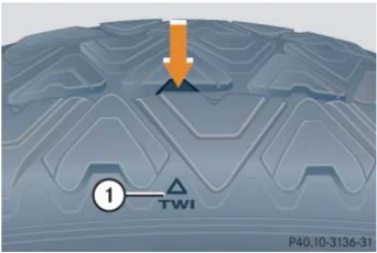
Treadwear indicators (TWI) are required by law. These indicators are located in six places on the tread circumference and become visible at a tread depth of approximately 1/16 in (1.6 mm), at which point the tire is considered worn and should be replaced.
Recommended minimum tire tread depth:
- Summer tires 1/8 in (3 mm)
- Winter tires 1/6 in (4 mm)
Warning!
Although the applicable federal motor safety laws consider a tire to be worn when the treadwear indicators (TWI) become visible at approximately 1/16 in (1.6 mm), we recommend that you do not allow your tires to wear down to that level. As tread depth approaches 1/8 in (3 mm), the adhesion properties on a wet road are sharply reduced.
Depending upon the weather and/or road surface (conditions), the tire traction varies widely.

① TWI (Tread Wear Indicator)
The treadwear indicator appears as a solid band across the tread.
Storing tires
! Keep unmounted tires in a cool, dry place with as little exposure to light as possible. Protect tires from contact with oil, grease and gasoline.
Cleaning tires
! Never use a round nozzle to power wash tires. The intense jet of water can result in damage to the tire.
Always replace a damaged tire.
306
Operation
Tires and wheels
Direction of rotation
Unidirectional tires offer added advantages, such as better hydroplaning performance. To benefit, however, you must make sure the tires rotate in the direction specified.
An arrow on the sidewall indicates the intended direction of rotation (spinning) of the tire.
i Spare wheels may be mounted against the direction of rotation (spinning) even with a unidirectional tire for temporary use only until the regular drive wheel has been repaired or replaced. Always observe and follow applicable temporary use restrictions and speed limitations indicated on the spare wheel.
Loading the vehicle
Two labels on your vehicle show how much weight it may properly carry.
-
The Tire and Loading Information placard (Example A) or the Vehicle Tire Information placard (Example B) can be found on the driver’s door B-pillar. This placard tells you important information about the number of people that can be in the vehicle and the total weight that can be carried in the vehicle. It also contains information on the proper size and recommended tire inflation pressures for the original equipment tires on your vehicle.
-
The Certification label, also found on the driver’s door B-pillar tells you about the gross weight capacity of your vehicle, called the Gross Vehicle Weight Rating (GVWR). The GVWR includes the weight of the vehicle, all occupants, fuel and cargo. The Certification label also tells you about the front and rear axle weight capacity, called the Gross Axle Weight Rating (GAWR). The GAWR is the total allowable weight that can be carried by a single axle (front or rear). Never exceed the GVWR or GAWR for either the front axle or rear axle.
307
Operation
Tires and wheels
 ① Driver’s door B-pillar
Following is a discussion on how to work with the information contained on the two placards with regards to loading your vehicle.
Tire and Loading Information
Warning!
Do not overload the tires by exceeding the specified load limit or vehicle capacity weight as indicated on the placard on the driver’s door B-pillar. Overloading the tires can overheat them, possibly causing a blowout. Overloading the tires can also result in handling or steering problems, or brake failure.
Your vehicle is equipped with either the Tire and Loading Information placard (Example A) or the Vehicle Tire Information placard (Example B).
Data shown on placard examples is for illustration purposes only. Load limit data is specific to each vehicle and may vary from data shown in the illustrations below. Refer to placard on vehicle for actual data specific to your vehicle.
Placard (Example A)
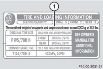
① Load limit information on the Tire and Loading Information placard
The placard showing the load limit information is located on the driver’s door B-pillar. If your vehicle is equipped with the Tire and Loading Information placard (Example A), locate the statement “The combined weight of occupants and cargo should never exceed XXX kilograms or XXX lbs.” on this placard. The combined weight of all occupants, cargo / luggage and trailer tongue load (if applicable) should never exceed the weight referenced in that statement.
308
Operation
Tires and wheels
Placard (Example B)
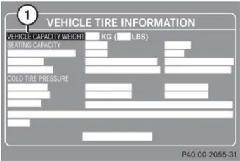
① Load limit information on the Vehicle Tire Information placard
The placard showing the load limit information is located on the driver’s door B-pillar. If your vehicle is equipped with the Vehicle Tire Information placard (Example B), locate the heading “Vehicle Capacity Weight” on this placard. The combined weight of all occupants, cargo/luggage and trailer tongue (if applicable) should never exceed the weight listed next to vehicle capacity weight.
Seating capacity
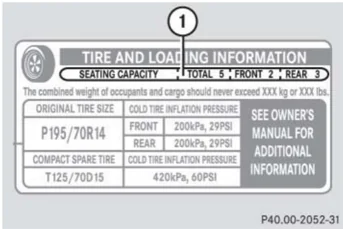
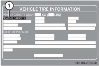
The seating capacity gives you important information on the number of occupants that can be in the vehicle. Observe front and rear seating capacity. Your vehicle is equipped with either placard Example A or placard Example B located on the driver’s door B-pillar (▷ page 308).
Data shown on placard examples is for illustration purposes only. Seating data is specific to each vehicle and may vary from data shown in the illustrations below. Refer to placard on vehicle for actual data specific to your vehicle.

P40.00-2052-31
Placard (Example A) ① Seating capacity
P40.00-2056-31
Placard (Example B) ① Seating capacity
309
Operation
Tires and wheels
Steps for determining correct load limit
The following steps have been developed as required of all manufacturers under Title 49, Code of U.S. Federal Regulations, Part 575 pursuant to the “National Traffic and Motor Vehicle Safety Act of 1966”.
Step 1 (Vehicles equipped with placard Example A)
- Locate the statement “The combined weight of occupants and cargo should never exceed XXX kg or XXX lbs.” on your vehicle’s placard.
Step 1 (Vehicles equipped with placard Example B)
- Locate the heading “Vehicle Capacity Weight” on your vehicle’s placard.
Step 2
- Determine the combined weight of the driver and passengers that will be riding in your vehicle.
Step 3
- Subtract the combined weight of the driver and passengers from XXX kilograms or XXX lbs.
Step 4
- The resulting figure equals the available amount of cargo and luggage load capacity. For example, if the “XXX” amount equals 1400 lbs and there will be five 150 lbs passengers in your vehicle, the amount of available cargo and luggage load capacity is 650 lbs (1400-750 (5 x150) = 650 lbs).
Step 5
- Determine the combined weight of luggage and cargo being loaded on the vehicle. That weight may not safely exceed the available cargo and luggage load capacity calculated in step 4.
Step 6 (if applicable)
- If your vehicle will be towing a trailer, load from your trailer will be transferred to your vehicle. Consult this manual to determine how this reduces the available cargo and luggage load capacity of your vehicle (\triangleright page 312).
The following table shows examples on how to calculate total and cargo load capacities with varying seating configurations and number and size of occupants. The following examples use a load limit of 1500 lbs. This is for illustration purposes only. Make sure you are using the actual load limit for your vehicle stated on the vehicle’s placard (\triangleright page 308).
310
Operation
Tires and wheels
| Example | Combined weight limit of occupants and cargo from placard | Number of occupants (driver and passengers) | Seating configuration | Occupants weight | Combined weight of all occupants | Available cargo/luggage and trailer tongue weight (total load limit or vehicle capacity weight from placard minus combined weight of all occupants) |
|---|---|---|---|---|---|---|
| 1 | 1500 lbs | 5 | front: 2rear: 3 | Occupant 1: 150 lbsOccupant 2: 180 lbsOccupant 3: 160 lbsOccupant 4: 140 lbsOccupant 5: 120 lbs | 750 lbs | 1500 lbs - 750 lbs = 750 lbs |
| 2 | 1500 lbs | 3 | front: 1rear: 2 | Occupant 1: 200 lbsOccupant 2: 190 lbsOccupant 3: 150 lbs | 540 lbs | 1500 lbs - 540 lbs = 960 lbs |
| 3 | 1500 lbs | 1 | front: 1 | Occupant 1: 150 lbs | 150 lbs | 1500 lbs - 150 lbs = 1350 lbs |
The higher the weight of all occupants, the less cargo and luggage load capacity is available.
For more information, see “Trailer tongue load” (▷ page 312).
311
Operation
Tires and wheels
Certification label
Even after careful determination of the combined weight of all occupants, cargo and the trailer tongue load (if applicable) (▷ page 312) as to not exceed the permissible load limit, you must make sure that your vehicle never exceeds the Gross Vehicle Weight Rating (GVWR) and the Gross Axle Weight Rating (GAWR) for either the front or rear axle. You can obtain the GVWR and GAWR from the Certification label. The Certification Label can be found on the driver’s door B-pillar, see “Technical data” (▷ page 420).
Gross Vehicle Weight Rating (GVWR): The total weight of the vehicle, all occupants, all cargo, and the trailer tongue load (▷ page 312) must never exceed the GVWR.
Gross Axle Weight Rating (GAWR): The total allowable weight that can be carried by a single axle (front or rear).
To assure that your vehicle does not exceed the maximum permissible weight limits (GVWR and GAWR for front and rear axle), have the loaded vehicle (including driver, passengers and all cargo and, if applicable, trailer fully loaded) weighed on a suitable commercial scale.
Trailer tongue load
The tongue load of any trailer is an important weight to measure because it affects the load you can carry in your vehicle. If a trailer is towed, the tongue load must be added to the weight of all occupants riding and any cargo you are carrying in the vehicle. The tongue load typically is ten percent of the trailer weight and everything loaded in it.
Your Mercedes-Benz has been designed primarily to carry passengers and their cargo. Mercedes-Benz does not recommend trailer towing with your vehicle.
312
Operation
Tires and wheels
Recommended tire inflation pressure
Warning!
Follow recommended tire inflation pressures.
Do not underinflate tires. Underinflated tires wear excessively and / or unevenly, adversely affect handling and fuel economy, and are more likely to fail from being overheated.
Do not overinflate tires. Overinflated tires can adversely affect handling and ride comfort, wear unevenly, increase stopping distance, and result in sudden deflation (blowout) because they are more likely to become punctured or damaged by road debris, potholes etc.
Your vehicle is equipped with either the Tire and Loading Information placard (Example A) or the Vehicle Tire Information placard (Example B) located on the driver’s door B-pillar (▷ page 308).
The tire inflation pressure should be checked regularly and should only be adjusted on cold tires. The tires can be considered cold if the vehicle has been parked for at least three hours or driven less than one mile (1.6 km).
Follow recommended cold tire inflation pressures listed on placard.
Keeping the tires properly inflated provides the best handling, tread life and riding comfort.
In addition to the tire placard on the driver’s door B-pillar, also consult the fuel filler flap for any additional information pertaining to special driving situations. For more information, see “Important notes on tire inflation pressure” (▷ page 314).
Data shown on placard examples is for illustration purposes only. Tire data is specific to each vehicle and may vary from data shown in the illustrations below. Refer to placard on vehicle for actual data specific to your vehicle.
313
Operation
Tires and wheels
Placard (Example A)
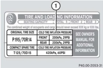
① Tire and Loading Information placard with recommended cold tire inflation pressures
Placard (Example A) lists the recommended cold tire inflation pressures for maximum loaded vehicle weight. The tire inflation pressures listed apply to the tires installed as original equipment.
Placard (Example B)
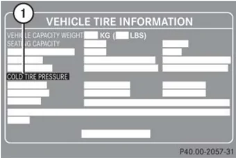
① Vehicle Tire Information placard with recommended cold tire inflation pressures
Placard (Example B) lists the recommended cold tire inflation pressures for maximum loaded vehicle weight. The tire inflation pressures listed apply to the tires installed as original equipment.
i Placard (Example B) may list recommended cold tire inflation pressures for different vehicle loads.
Important notes on tire inflation pressure
Warning!
If the tire inflation pressure repeatedly drops:
- Check the tires for punctures from foreign objects.
- Check to see whether air is leaking from the valves or from around the rim.
Tire temperature and tire inflation pressure are also increased while driving, depending on the driving speed and the tire load.
If you will be driving your vehicle at high speeds of 100 mph (160 km/h) or higher, where it is legal and conditions allow, consult the placard on the inside of the fuel filler flap on how to adjust the cold tire inflation pressure. If you do not adjust the tire inflation pressure, excessive heat can build up and result in sudden tire failure.
314
Operation
Tires and wheels
Be sure to readjust the tire inflation pressure for normal driving speeds. You should wait until the tires are cold before adjusting the tire inflation pressure.
Some vehicles may have supplemental tire inflation pressure information for vehicle loads less than the maximum loaded vehicle condition. If such information is provided, it can be found on the placard located on the inside of the fuel filler flap.
Tire inflation pressure changes by approximately 1.5 psi (0.1 bar) per 18°F (10°C) of air temperature change. Keep this in mind when checking tire inflation pressure where the temperature is different from the outside temperature.
Checking tire inflation pressure
Regularly check your tire inflation pressure at least once a month.
Check and adjust the tire inflation pressure when the tires are cold. The tires can be considered cold if the vehicle has been parked for at least three hours or driven less than one mile (1.6 km).
If you check the tire inflation pressure when the tires are warm (the vehicle has been driven for several miles or sitting less than three hours), the reading will be approximately 4 psi (0.3 bar) higher than the cold reading. This is normal. Do not let air out to match the specified cold tire inflation pressure. Otherwise, the tire will be underinflated.
Follow the steps below to achieve correct tire inflation pressure:
▶ Remove the cap from the valve on one tire.
▶ Firmly press a tire gauge onto the valve.
▶ Read tire inflation pressure on tire gauge and check against the recommended tire inflation pressure on the placard on the driver’s door B-pillar (> page 314). If necessary, add air to achieve the recommended tire inflation pressure.
▷▷
315
Operation
Tires and wheels
If you have overfilled the tire, release tire inflation pressure by pushing the metal stem of the valve with e.g. a tip of a pen. Then recheck the tire inflation pressure with the tire gauge.
▶ Install the valve cap.
▶ Repeat this procedure for each tire.
The recommended tire inflation pressures for your vehicle can be found on the tire placard located on the driver’s door B-pillar. The tire inflation pressures are not listed in the owner’s manual.
Warning!
Follow recommended tire inflation pressures.
Do not overinflate tires. Overinflating tires can result in sudden deflation (blowout) because they are more likely to become punctured or damaged by road debris, potholes, etc.
Do not underinflate tires. Underinflated tires wear unevenly, adversely affect handling and fuel economy, and are more likely to fail from being overheated.
Do not overload the tires by exceeding the specified load limit or vehicle capacity weight as indicated on the placard on the driver’s door B-pillar. Overloading the tires can overheat them, possibly causing a blowout.
Potential problems associated with underinflated and overinflated tires
Underinflated tire inflation pressure
Underinflated tires can:
• cause excessive and uneven tire wear
• adversely affect fuel economy
• lead to tire failure from being overheated
• adversely affect handling characteristics
Warning!
Follow recommended tire inflation pressures.
Do not underinflate tires. Underinflated tires wear excessively and /or unevenly, adversely affect handling and fuel economy, and are more likely to fail from being overheated.
316
Operation
Tires and wheels
Overinflated tire inflation pressure
Overinflated tires can:
- adversely affect handling characteristics
- cause uneven tire wear
- be more prone to damage from road hazards
- adversely affect ride comfort
- increase stopping distance
Warning! Follow recommended tire inflation pressures.
Do not overinflate tires. Overinflated tires can adversely affect handling and ride comfort, wear unevenly, increase stopping distance, and result in sudden deflation (blowout) because they are more likely to become punctured or damaged by road debris, potholes etc.
Tire labeling
Besides tire name (sales designation) and manufacturer name, a number of markings can be found on a tire.
Following are some explanations for the markings on your vehicle’s tires:
 P40.10-3561-31
① Uniform Quality Grading Standards (> page 325) ② DOT, Tire Identification Number (TIN) (> page 322) ③ Maximum tire load (> page 323) ④ Maximum tire inflation pressure (> page 324) ⑤ Manufacturer ⑥ Tire ply material (> page 327) ⑦ Tire size designation, load and speed rating (> page 318) ⑧ Load identification (> page 321) ⑨ Tire name
For illustration purposes only. Actual data on tires is specific to each vehicle and may vary from data shown in above illustration.
For more information, see “Rims and Tires” (> page 424).
317
Operation
Tires and wheels
Tire size designation, load and speed rating
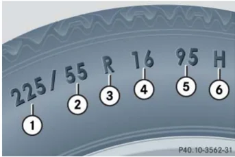
① Tire width ② Aspect ratio in % ③ Radial tire code ④ Rim diameter ⑤ Tire load rating ⑥ Tire speed rating
General:
Depending on the design standards used, the tire size molded into the sidewall may have no letter or a letter preceding the tire size designation.
No letter preceding the size designation (as illustrated above): Passenger car tire based on European design standards.
Letter “P” preceding the size designation: Passenger car tire based on U.S. design standards.
Letter “LT” preceding the size designation: Light Truck tire based on U.S. design standards.
Letter “T” preceding the size designation: Temporary spare tires which are high pressure compact spares designed for temporary emergency use only.
Tire width
The tire width ① (> page 318) indicates the nominal tire width in mm.
Aspect ratio
The aspect ratio ② (> page 318) is the dimensional relationship between tire section height and section width and is expressed in percentage. The aspect ratio is arrived at by dividing section height by section width.
Tire code
The tire code ③ (> page 318) indicates the tire construction type. The “R” stands for radial tire type. Letter “D” means diagonal or bias ply construction; letter “B” means belted-bias ply construction.
At the tire manufacturer’s option, any tire with a speed capability above 149 mph (240 km/h) can include a “ZR” in the size designation (for example: 245/40 ZR 18). For additional information, see “Tire speed rating” (> page 320).
For illustration purposes only. Actual data on tires is specific to each vehicle and may vary from data shown in above illustration.
318
Operation
Tires and wheels
Rim diameter The rim diameter ④ (▷ page 318) is the diameter of the bead seat, not the diameter of the rim edge. Rim diameter is indicated in inches (in).
Tire load rating The tire load rating ⑤ (▷ page 318) is a numerical code associated with the maximum load a tire can support.
For example, a load rating of 91 corresponds to a maximum load of 1356 lbs (615 kg) the tire is designed to support. See also "Maximum tire load" (▷ page 323) where the maximum load associated with the load index is indicated in kilograms and lbs.
Warning The tire load rating must always be at least half of the GAWR (▷ page 328) of your vehicle. Otherwise, tire failure may be the result which may cause an accident and/or serious personal injury to you or others.
Always replace rims and tires with the same designation, manufacturer and type as shown on the original part.
Warning! Do not overload the tires by exceeding the specified load limit or vehicle capacity weight as indicated on the placard located on the driver's door B-pillar. Overloading the tires can overheat them, possibly causing a blowout. Overloading the tires can also result in handling or steering problems, or brake failure.
For additional information on tire load rating, see "Load identification" (▷ page 321).
Tire load rating ⑤ (▷ page 318) and Tire speed rating ⑥ (▷ page 318) are also referred to as "service description".
319
Operation
Tires and wheels
Tire speed rating
The tire speed rating ⑥ (▷ page 318) indicates the approved maximum speed for the tire.
Warning!
Even when permitted by law, never operate a vehicle at speeds greater than the maximum speed rating of the tires.
Exceeding the maximum speed for which tires are rated can lead to sudden tire failure, causing loss of vehicle control and possibly resulting in an accident and/or personal injury and possible death, for you and for others.
Tire load rating ⑤ (▷ page 318) and Tire speed rating ⑥ (▷ page 318) are also referred to as “service description”.
Summer tires
- At the tire manufacturer’s option, any tire with a speed capability above 149 mph (240 km/h) can include a “ZR” in the size designation (for example: 245/40 ZR18). To determine the maximum speed capability of the tire, the service description for the tire must be referred to. The service description is comprised of the tire load rating ⑤ (▷ page 318) and the tire speed rating ⑥ (▷ page 318).
If your tire includes “ZR” in the size designation and no service description ⑤ and ⑥ (▷ page 318) is given, the tire manufacturer must be consulted for the maximum speed capability.
Operation
Tires and wheels
If a service description ⑤ and ⑥ (▷ page 318) is given, the speed capability is limited by the speed symbol in the service description.
Example: 245/40 ZR18 97Y.
In this example, “97Y” is the service description. The letter “Y” designates the speed rating and the speed capability of the tire is limited to 186 mph (300 km/h).
- Any tire with a speed capability above 186 mph (300 km/h) must include a “ZR” in the size designation AND the service description must be placed in parenthesis. Example: 275/40 ZR 18 (99Y). The “(Y)” speed rating in parenthesis designates the maximum speed capability of the tire as being above 186 mph (300 km/h). Consult the tire manufacturer for the actual maximum permissible speed of the tire.
All-season and winter tires
| Index | Speed rating |
|---|---|
| Q M+S | up to 100 mph (160 km/h) |
| T M+S | up to 118 mph (190 km/h) |
| H M+S | up to 130 mph (210 km/h) |
| V M+S | up to 149 mph (240 km/h) |
The marking “M+S” next to the service description designates tires with mud and snow capabilities.
Load identification
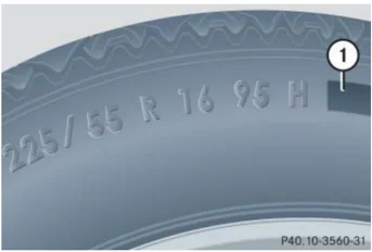
① Load identification
For illustration purposes only. Actual data on tires is specific to each vehicle and may vary from data shown in above illustration.
321
Operation
Tires and wheels
In addition to tire load rating, special load information may be molded into the tire sidewall following the letter designating the tire speed rating ① (▷ page 321).
No specification given: absence of any text (like in above example) indicates a standard load (SL) tire.
XL or Extra Load: designates an extra load (or reinforced) tire.
Light Load: designates a light load tire.
C, D, E: designates load range associated with the maximum load a tire can carry at a specified pressure.
DOT, Tire Identification Number (TIN)
U.S. tire regulations require each new tire manufacturer or tire retreader to mold a TIN into or onto a sidewall of each tire produced.
The TIN is a unique identifier which facilitates efforts by tire manufactures to notify purchasers in recall situations or other safety matters concerning tires and gives purchasers the means to easily identify such tires.
The TIN is comprised of “Manufacturer’s identification mark”, “Tire size”, “Tire type code”, and “Date of manufacture”.
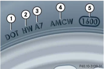
① DOT ② Manufacturer’s identification mark ③ Tire size ④ Tire type code (at the option of the tire manufacturer) ⑤ Date of manufacture
For illustration purposes only. Actual data on tires is specific to each vehicle and may vary from data shown in above illustration.
322
Operation
Tires and wheels
DOT (Department of Transportation) A tire branding symbol ① (> page 322) which denotes the tire meets requirements of the U.S. Department of Transportation.
Manufacturer’s identification mark The manufacturer’s identification mark ② (> page 322) denotes the tire manufacturer.
New tires have a mark with two symbols. Retreaded tires have a mark with four symbols. For more information on retreaded tires, see (> page 304).
Tire size The code ③ (> page 322) indicates the tire size.
Tire type code The code ④ (> page 322) may, at the option of the manufacturer, be used as a descriptive code for identifying significant characteristics of the tire.
Date of manufacture The date of manufacture ⑤ (> page 322) identifies the week and year of manufacture.
The first two figures identify the week, starting with “01” to represent the first full week of the calendar year. The second two figures represent the year.
For example, “3202” represents the 32nd week of 2002.
Maximum tire load

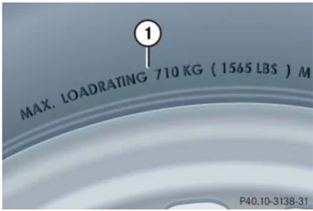
① Maximum tire load rating
For illustration purposes only. Actual data on tires is specific to each vehicle and may vary from data shown in above illustration.
The maximum tire load is the maximum weight the tires are designed to support.
323
Operation
Tires and wheels
Warning!
Do not overload the tires by exceeding the specified load limit or vehicle capacity weight as indicated on the placard located on the driver’s door B-pillar. Overloading the tires can overheat them, possibly causing a blowout. Overloading the tires can also result in handling or steering problems, or brake failure.
For more information on tire load rating (▷ page 319).
For information on calculating total and cargo load capacities (▷ page 310).
Maximum tire inflation pressure
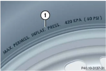
① Maximum permissible tire inflation pressure
For illustration purposes only. Actual data on tires is specific to each vehicle and may vary from data shown in above illustration.
This is the maximum permissible tire inflation pressure for the tire.
Always follow the recommended tire inflation pressure (▷ page 313) for proper tire inflation.
Warning!
Never exceed the max. tire inflation pressure. Follow recommended tire inflation pressures.
Do not underinflate tires. Underinflated tires wear excessively and / or unevenly, adversely affect handling and fuel economy, and are more likely to fail from being overheated.
Do not overinflate tires. Overinflated tires can adversely affect handling and ride comfort, wear unevenly, increase stopping distance, and result in sudden deflation (blowout) because they are more likely to become punctured or damaged by road debris, potholes etc.
324
Uniform Tire Quality Grading Standards (U.S. vehicles)
Tire manufacturers are required to grade tires based on three performance factors: treadwear, traction, and temperature resistance.
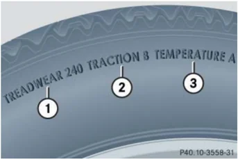
① Treadwear
② Traction
③ Temperature resistance
For illustration purposes only. Actual data on tires is specific to each vehicle and may vary from data shown in above illustration.
Quality grades can be found, where applicable, on the tire sidewall between tread shoulder and maximum section width. For example:
| Treadwear | Traction | Temperature |
|---|---|---|
| 200 | AA | A |
All passenger car tires must conform to federal safety requirements in addition to these grades.
Operation
Tires and wheels
Treadwear
The treadwear grade is a comparative rating based on the wear rate of the tire when tested under controlled conditions on a specified government test course. For example, a tire graded 150 would wear one and one-half (1-1/2) times as well on the government course as a tire graded 100. The relative performance of tires depends upon the actual conditions of their use, however, and may depart significantly from the norm due to variations in driving habits, service practices and differences in road characteristics and climate.
325