8 Maintenance and do-it-yourself
- Maintenance requirements ........ 8-2
- General maintenance ........ 8-2
- Explanation of general maintenance items ........ 8-2
- Maintenance precautions ........ 8-5
- Engine compartment check locations ........ 8-7
- Engine cooling system ........ 8-8
- Checking engine coolant level ........ 8-8
- Changing engine coolant ........ 8-9
- Engine oil ........ 8-10
- Checking engine oil level ........ 8-10
- Changing engine oil and filter ........ 8-10
- Automatic transmission fluid ........ 8-12
- Power steering fluid ........ 8-13
- Brake and clutch fluid ........ 8-13
- Brake fluid ........ 8-14
- Clutch fluid ........ 8-14
- Window washer fluid ........ 8-14
- Battery ........ 8-15
- Jump starting ........ 8-17
- Drive belts ........ 8-17
- Spark plugs ........ 8-18
- Replacing spark plugs ........ 8-18
- Air cleaner ........ 8-18
- Windshield wiper blades ........ 8-19
- Cleaning ........ 8-19
- Replacing ........ 8-20
- Parking brake and brake pedal ........ 8-21
- Checking parking brake ........ 8-21
- Checking brake pedal ........ 8-21
- Brake booster ........ 8-22
- Fuses ........ 8-22
- Engine compartment ........ 8-23
- Passenger compartment ........ 8-24
- Keyfob battery replacement ........ 8-25
- Lights ........ 8-26
- Headlights ........ 8-27
- Exterior and interior lights ........ 8-28
- Wheels and tires ........ 8-30
- Tire pressure ........ 8-30
- Tire labeling ........ 8-34
- Types of tires ........ 8-36
- Tire chains ........ 8-37
- Changing wheels and tires ........ 8-37
MAINTENANCE REQUIREMENTS
Your new NISSAN has been designed to have minimum maintenance requirements with longer service intervals to save you both time and money. However, some day-to-day and regular maintenance is essential to maintain your NISSAN's good mechanical condition, as well as its emission and engine performance.
It is the owner's responsibility to make sure that scheduled maintenance, as well as general maintenance, is performed.
As the vehicle owner, you are the only one who can ensure that your vehicle receives the proper maintenance care. You are a vital link in the maintenance chain.
Scheduled maintenance:
For your convenience, both required and optional scheduled maintenance items are described and listed in your "NISSAN Service and Maintenance Guide". You must refer to that guide to ensure that necessary maintenance is performed on your NISSAN at regular intervals.
General maintenance:
General maintenance includes those items which should be checked during normal day-to-day operation. They are essential for proper vehicle operation. It is your responsibility to perform these procedures regularly as prescribed.
8-2 Maintenance and do-it-yourself
10% 20% 30% 40% 50% 60% 70% 80% 90%
Performing general maintenance checks requires minimal mechanical skill and only a few general automotive tools.
These checks or inspections can be done by yourself, a qualified technician or, if you prefer, a NISSAN dealer.
Where to go for service:
If maintenance service is required or your vehicle appears to malfunction, have the systems checked and tuned by a NISSAN dealer.
NISSAN technicians are well-trained specialists and are kept up to date with the latest service information through technical bulletins, service tips, and in-dealership training programs. They are completely qualified before they work on your vehicle, rather than after they have worked on it.
You can be confident that a NISSAN dealer's service department performs the best job to meet the maintenance requirements of your vehicle — in a reliable and economic way.
GENERAL MAINTENANCE
During the normal day-to-day operation of the vehicle, general maintenance should be performed regularly as prescribed in this section. If you detect any unusual sounds, vibrations or smells, be sure to check for the cause or have a NISSAN dealer do it promptly. In addition, you should notify a NISSAN dealer if you think that repairs are required.
When performing any checks or maintenance work, closely observe the "Maintenance precautions" later in this section.
EXPLANATION OF GENERAL MAINTENANCE ITEMS
Additional information on the following items with "•••" is found later in this section.
Outside the vehicle
The maintenance items listed here should be performed from time to time, unless otherwise specified.
Doors and engine hood: Check that all doors and the engine hood operate smoothly as well as the trunk lid or back hatch. Also make sure that all latches lock securely. Lubricate if necessary. Make sure that the secondary latch keeps the hood from opening when the primary latch is released.
When driving in areas using road salt or other
corrosive materials, check lubrication frequently.
Lights*: Clean the headlights on a regular basis. Make sure that the headlights, stop lights, tail lights, turn signal lights, and other lights are all operating properly and installed securely. Also check headlight aim.
Road wheel nuts (lug nuts)*: When checking the tires, make sure no nuts are missing, and check for any loose nuts. Tighten if necessary.
Tire rotation*: Tires cannot be rotated in this vehicle.
Tire, wheel alignment and balance: If the vehicle pulls to either side while driving on a straight and level road, or if you detect uneven or abnormal tire wear, there may be a need for wheel alignment.
If the steering wheel or seat vibrates at normal highway speeds, wheel balancing may be needed.
For additional information regarding tires, refer to "Important Tire Safety Information" (US) or "Tire Safety Information" (Canada) in the Warranty Information Booklet.
Tires*: Check the pressure with a gauge often and always prior to long distance trips. Adjust the pressure in all tires, including the spare, to the pressure specified. Check carefully for dam-
age, cuts or excessive wear.
Windshield: Clean the windshield on a regular basis. Check the windshield at least every six months for cracks or other damage. Have a damaged windshield repaired by a qualified repair facility.
Windshield wiper blades*: Check for cracks or wear if they do not wipe properly.
Inside the vehicle
The maintenance items listed here should be checked on a regular basis, such as when performing periodic maintenance, cleaning the vehicle, etc.
Automatic transmission P (Park) position mechanism: On a fairly steep hill check that the vehicle is held securely with the selector lever in the P (Park) position without applying any brakes.
Accelerator pedal: Check the pedal for smooth operation and make sure the pedal does not catch or require uneven effort. Keep the floor mat away from the pedal.
Brakes: Check that the brakes do not pull the vehicle to one side when applied.
Brake pedal and booster*: Check the pedal for smooth operation and make sure it has the proper distance under it when depressed fully.
Check the brake booster function. Be sure to keep floor mat away from the pedal.
Parking brake*: Check that the lever/pedal has the proper travel and make sure that the vehicle is held securely on a fairly steep hill when only the parking brake is applied.
Seats: Check seat position controls such as seat adjusters, seatback recliner, etc. to ensure they operate smoothly and that all latches lock securely in every position. Check that the head restraints move up and down smoothly and that the locks (if equipped) hold securely in all latched positions.
Seat belts: Check that all parts of the seat belt system (for example, buckles, anchors, adjusters and retractors) operate properly and smoothly, and are installed securely. Check the belt webbing for cuts, fraying, wear or damage.
Steering wheel: Check for changes in the steering conditions, such as excessive free play, hard steering or strange noises.
Warning lights and chimes: Make sure that all warning lights and chimes are operating properly.
Windshield wiper and washer*: Check that the wipers and washer operate properly and that the wipers do not streak.
Maintenance and do-it-yourself 8-3
Windshield defroster: Check that the air comes out of the defroster outlets properly and in good quantity when operating the heater or air conditioner.
Under the hood and the vehicle
The maintenance items listed here should be checked periodically (for example, each time you check the engine oil or refuel).
Battery*: Check the fluid level in each cell. It should be between the MAX and MIN lines. Vehicles operated in high temperatures or under severe conditions require frequent checks of the battery fluid level.
Brake and clutch fluid levels*: Make sure that the brake and clutch fluid levels are between the MAX and MIN lines on the reservoir.
Engine coolant level*: Check the coolant level when the engine is cold.
Engine drive belts*: Make sure that no belt is frayed, worn, cracked or oily.
Engine oil level*: Check the level on the dipstick after parking the vehicle on a level spot, turning off the engine and waiting 10 minutes.
Exhaust system: Make sure there are no loose supports, cracks or holes. If the sound of the exhaust seems unusual or there is a smell of exhaust fumes, immediately locate the trouble and correct it. (See "Precautions when starting and driving" in the "5. Starting and driving" section for exhaust gas (carbon monoxide).)
Fluid leaks: Check under the vehicle for fuel, oil, water or other fluid leaks after the vehicle has been parked for a while. Water dripping from the air conditioner after use is normal. If you should notice any leaks or if gasoline fumes are evident, check for the cause and have it corrected immediately.
Power steering fluid level* and lines: Check the level in the reservoir tank with the engine off. Check the lines for proper attachment, leaks, cracks, etc.
Radiator and hoses: Check the front of the radiator and clean off any dirt, insects, leaves, etc., that may have accumulated. Make sure the hoses have no cracks, deformation, deterioration or loose connections.
Underbody: The underbody is frequently exposed to corrosive substances such as those used on icy roads or to control dust. It is very important to remove these substances, otherwise rust will form on the floor pan, frame, fuel lines and around the exhaust system. At the end of winter, the underbody should be thoroughly flushed with plain water, being careful to clean those areas where mud and dirt may accumulate. For additional information, see "Cleaning exterior" in the "7. Appearance and care" section.
Window washer fluid*: Check that there is adequate fluid in the tank.
8-4 Maintenance and do-it-yourself
MAINTENANCE PRECAUTIONS
When performing any inspection or maintenance work on your vehicle, always take care to prevent serious accidental injury to yourself or damage to the vehicle. The following are general precautions which should be closely observed.
WARNING
- Park the vehicle on a level surface, apply the parking brake securely and block the wheels to prevent the vehicle from moving. For manual transmission models, move the shift lever to N (Neutral) position. For automatic transmission models, move the selector lever to P (Park).
- Be sure the ignition key is in the OFF or LOCK position when performing any parts replacement or repairs.
- Never connect or disconnect the battery or any transistorized component while the ignition switch is in the ON position.
- Never leave the engine or automatic transmission related component harnesses disconnected while the ignition switch is in the ON position.
- If you must work with the engine running, keep your hands, clothing, hair and tools away from moving fans, belts and any other moving parts.
- It is advisable to secure or remove any loose clothing and remove any jewelry, such as rings, watches, etc. before working on your vehicle.
- Always wear eye protection whenever you work on your vehicle.
- If you must run the engine in an enclosed space such as a garage, be sure there is proper ventilation for exhaust gases to escape.
- Never get under the vehicle while it is supported only by a jack. If it is necessary to work under the vehicle, support it with safety stands.
- Keep smoking materials, flame and sparks away from the fuel tank and battery.
- On gasoline engine models with the multiport fuel injection (MFI) system, the fuel filter or fuel lines should be serviced by a NISSAN dealer because the fuel lines are under high pressure even when the engine is off.
CAUTION
- Do not work under the hood while the engine is hot. Turn the engine off and wait until it cools down.
- Avoid contact with used engine oil and coolant. Improperly disposed engine oil, engine coolant and/or other vehicle fluids can damage the environment. Always conform to local regulations for disposal of vehicle fluid.
This "8. Maintenance and do-it-yourself" section gives instructions regarding only those items which are relatively easy for an owner to perform.
A genuine NISSAN Service Manual is also available. See "Owner's Manual/Service Manual or-
Maintenance and do-it-yourself 8-5
der information” in the “9. Technical and consumer information” section.
You should be aware that incomplete or improper servicing may result in operating difficulties or excessive emissions, and could affect your warranty coverage. If in doubt about any servicing, have it done by a NISSAN dealer.
8-6 Maintenance and do-it-yourself
ENGINE COMPARTMENT CHECK LOCATIONS
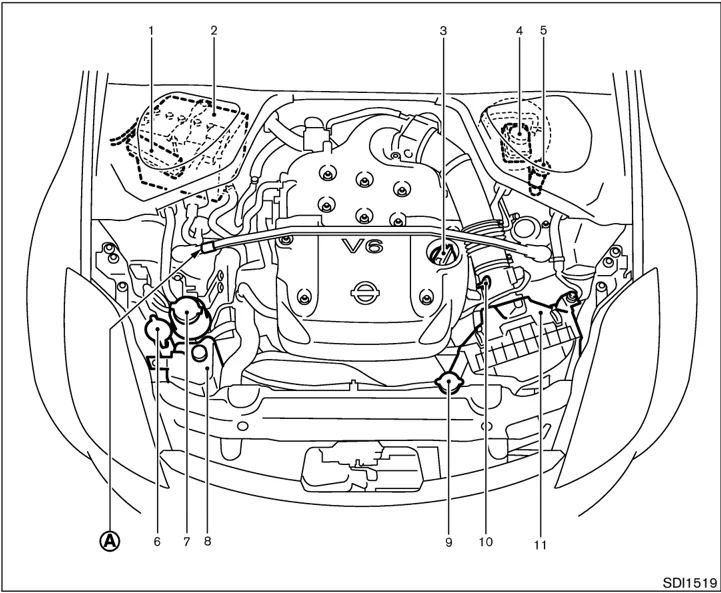
- Fuse/fusible link holder
- Battery
- Engine oil filler cap
- Brake fluid reservoir
- Clutch fluid reservoir (M/T models)
- Windshield washer fluid reservoir
- Power steering fluid reservoir
- Engine coolant reservoir
- Radiator filler cap
- Engine oil dipstick
- Air cleaner
Do not tamper with the strut tower bar adjustment A. The strut tower bar has been adjusted to the most suitable position at the factory.
CAUTION
Tampering with the strut tower bar adjustment may cause a noise while driving or damage to the hood or engine.
SDI1519
Maintenance and do-it-yourself 8-7
ENGINE COOLING SYSTEM
The engine cooling system is filled at the factory with a high-quality, year-round, anti-freeze coolant solution. The anti-freeze solution contains rust and corrosion inhibitors, therefore additional cooling system additives are not necessary.
WARNING
- Never remove the radiator or coolant reservoir cap when the engine is hot. Wait until the engine and radiator cool down. Serious burns could be caused by high pressure fluid escaping from the radiator. See precautions in “If your vehicle overheats” found in the “6. In case of emergency” section of this manual.
- The radiator is equipped with a pressure type radiator cap. To prevent engine damage, use only a genuine NISSAN radiator cap.
\begin{tabular}{|l|l|l|l|} \hline Outside temperature & & Anti- & Deminer- \ down to & & freeze & alized \ & & & water/ \ & & & distilled \ & & & water \ \hline °C & °F & & \ \hline $-$35 & $-$30 & 50% & 50% \ \hline \end{tabular}
CAUTION
When adding or replacing coolant, be sure to use only a Genuine NISSAN Long Life Antifreeze/Coolant (green) or equivalent with the proper mixture ratio of 50% anti-freeze and 50% demineralized water/distilled water. The use of other types of coolant solutions may damage your engine cooling system.
SDI1445
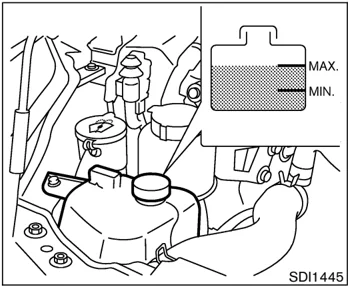
CHECKING ENGINE COOLANT LEVEL
Check the coolant level in the reservoir tank when the engine is cold. If the coolant level is below MIN, add coolant up to the MAX level. If the reservoir tank is empty, check the coolant level in the radiator when the engine is cold. If there is insufficient coolant in the radiator, fill the radiator with coolant up to the filler opening and also add it to the reservoir tank up to the MAX level.
If the engine cooling system frequently requires coolant, have it checked by a NISSAN dealer.
8-8 Maintenance and do-it-yourself
Front LOOSEN Radiator cap
Front LOOSEN Drain plug
SDI1442
CHANGING ENGINE COOLANT
-
Major cooling system repairs should be performed by a NISSAN dealer. The service procedures can be found in the appropriate NISSAN Service Manual.
-
Improper servicing can result in reduced heater performance and engine overheating.
WARNING
- To avoid being scalded, never change the coolant when the engine is hot.
- Never remove the radiator cap when the engine is hot. Serious burns could be caused by high pressure fluid escaping from the radiator.
- Avoid direct skin contact with used coolant. If skin contact is made, wash thoroughly with soap or hand cleaner as soon as possible.
- Keep coolant out of reach of children and pets.
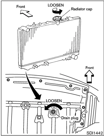
- Open radiator drain plug at the bottom of radiator, and remove radiator filler cap.
- Be careful not to allow coolant to contact drive belts.
- Waste coolant must be disposed of properly. Check your local regulations.
- Close the radiator drain plug securely after the coolant is drained.
- Fill the radiator slowly with the proper mixture of anti-freeze solution and demineralized water/distilled water. Fill the reservoir tank up to the MAX level. Then install the radiator filler cap.
- Start the engine and warm it up until it reaches normal operating temperature. Then race the engine 2 or 3 times under no load. Watch the engine coolant temperature gauge for signs of overheating.
- Stop the engine. After it completely cools down, refill the radiator up to the filler opening. Fill the reservoir tank up to the MAX level. Check the drain plug for any sign of leakage.
- Recheck the coolant level after the vehicle has been driven for a day.
Maintenance and do-it-yourself 8-9
ENGINE OIL
 SDI1386C
CHECKING ENGINE OIL LEVEL
- Park the vehicle on a level surface and apply parking brake.
- Run the engine until it reaches operating temperature.
- Turn off the engine. Wait more than 10 minutes for the oil to drain back into the oil pan.
- Remove the dipstick and wipe it clean. Reinsert it all the way.
 SDI1781
- Remove the dipstick again and check the oil level. It should be between the H and L marks (B). If the oil level is below the L mark (A), remove the oil filler cap and pour recommended oil through the opening. Do not overfill (C).
- Recheck oil level with dipstick.
It is normal to add some oil between oil maintenance intervals or during the break-in period, depending on the severity of operating conditions.
CAUTION
Oil level should be checked regularly. Operating the engine with insufficient amount of oil can damage the engine, and such damage is not covered by warranty.
CHANGING ENGINE OIL AND FILTER
Change the engine oil and filter according to the maintenance log shown in the Service and Maintenance Guide.
Vehicle set-up
- Park the vehicle on a level surface and apply the parking brake.
- Run the engine until it reaches operating temperature.
- Turn the engine off and wait more than 10 minutes.
- Raise and support the vehicle using a suitable floor jack and safety jack stands.
- Place the safety jack stands under the vehicle jack-up points.
8-10 Maintenance and do-it-yourself

- A suitable adapter should be attached to the jack stand saddle.
- Remove the plastic engine undercover. a. Remove the small plastic clip at the center point of the undercover. b. Then remove the other bolts that hold the undercover in place.
CAUTION Make sure the correct lifting and support points are used to avoid vehicle damage.

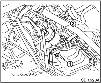
SDI1520A
Engine oil and filter
- Place a large drain pan under the drain plug ①.
- Remove the oil filler cap.
- Remove the drain plug with a wrench and completely drain the oil.
CAUTION Be careful not to burn yourself, as the engine oil is hot.
-
Waste oil must be disposed of properly.
-
Check your local regulations.
- Loosen the oil filter with an oil filter wrench ②. Remove the oil filter by turning it by hand.
- Wipe the engine oil filter mounting surface with a clean rag. Be sure to remove any old rubber gasket remaining on the mounting surface of the engine.
- Coat the gasket on the new filter with clean engine oil.
- Screw in the oil filter clockwise until a slight resistance is felt, then tighten additionally more than 2/3 turn. Oil filter tightening torque: 11 to 15 ft-lb (14.7 to 20.5 N·m)
- Clean and re-install the drain plug and a new washer. Securely tighten the drain plug with a wrench. Drain plug tightening torque: 22 to 29 ft-lb (29 to 39 N·m) Do not use excessive force.
- Refill engine with recommended oil and install the cap securely.
Maintenance and do-it-yourself 8-11
CAUTION
The dipstick must be inserted in place to prevent oil spillage from the dipstick hole while filling the engine with oil.
See “Capacities and recommended fuel/ lubricants” in the “9. Technical and consumer information” section for drain and refill capacity. The drain and refill capacity depends on the oil temperature and drain time. Use these specifications for reference only. Always use the dipstick to determine the proper amount of oil in the engine.
- Start the engine and check for leakage around the drain plug and the oil filter. Correct as required.
- Turn the engine off and wait more than 10 minutes. Check the oil level with the dipstick. Add engine oil if necessary.
After the operation
- Install the engine undercover into position as outlined in the following steps. a. Pull the center of the small plastic clip out. b. Hold the engine undercover into position. c. Insert the clip through the undercover into the hole in the frame, then push the center of the clip in to lock the clip in place. d. Install the other bolts that hold the undercover in place. Be careful not to strip the bolts or over-tighten them.
- Lower the vehicle carefully to the ground.
- Dispose of waste oil and filter properly.
WARNING
- Prolonged and repeated contact with used engine oil may cause skin cancer.
- Try to avoid direct skin contact with used oil. If skin contact is made, wash thoroughly with soap or hand cleaner as soon as possible.
- Keep used engine oil out of reach of children.
AUTOMATIC TRANSMISSION FLUID
When checking or replacement is required, we recommend a NISSAN dealer for servicing.
CAUTION
- Use only Genuine NISSAN Matic J ATF. Do not mix with other fluids.
- Using automatic transmission fluid other than Genuine NISSAN Matic J ATF will cause deterioration in drive-ability and automatic transmission durability, and may damage the automatic transmission, which is not covered by the NISSAN new vehicle limited warranty.
The specified automatic transmission fluid is also described on caution labels located in the engine compartment.
8-12 Maintenance and do-it-yourself
POWER STEERING FLUID
 SDI1443
Check the fluid level in the reservoir tank.
The fluid level should be checked using the HOT range at fluid temperatures of 122 - 176°F (50 - 80°C) or using the COLD range at fluid temperatures of 32 - 86°F (0 - 30°C).
If the fluid is below the MIN line, add Genuine NISSAN PSF fluid. Remove the cap and fill through the opening.
CAUTION
- Do not overfill.
- Recommended fluid is Genuine NISSAN PSF or equivalent.
BRAKE AND CLUTCH FLUID
For additional brake and clutch fluid information, refer to "Capacities and recommended fuel/ lubricants" in the "9. Technical and consumer information" section of this manual.
WARNING
Use only new fluid. Old, inferior or contaminated fluid may damage the brake system. Do not add synthetic brake fluid. The use of improper fluids can damage the brake system and affect the vehicle's stopping ability.
CAUTION
Do not spill the fluid on any painted surfaces. This will damage the paint. If fluid is spilled, immediately wash the surface with water.
Maintenance and do-it-yourself 8-13
BRAKE FLUID
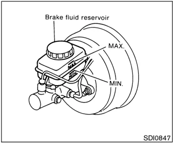
Check the fluid level in the reservoir. If the fluid is below the MIN line or the brake warning light comes on, add Genuine NISSAN Super Heavy Duty Brake Fluid or equivalent DOT 3 fluid up to the MAX line. If fluid must be added frequently, the system should be thoroughly checked by a NISSAN dealer.
CLUTCH FLUID
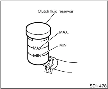
Check the fluid level in the reservoir. If the fluid level is below the MIN. line, add Genuine NISSAN Super Heavy Duty Brake Fluid or equivalent DOT 3 fluid up to the MAX. line.
If fluid is added frequently, the system should be thoroughly checked by a NISSAN dealer.
WINDOW WASHER FLUID
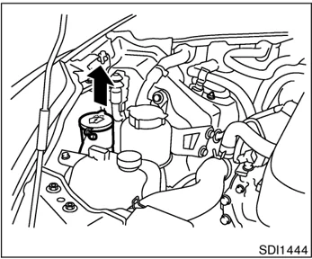
Open the cap and add fluid when the low washer fluid warning light comes on.
Add a washer solvent to the washer fluid for better cleaning. In the winter season, add a windshield washer anti-freeze. Follow the manufacturer's instructions for the mixture ratio.
Recommended fluid is Genuine NISSAN Windshield Washer Concentrate Cleaner & Anti-freeze or equivalent.
8-14 Maintenance and do-it-yourself
WARNING
Anti-freeze is poisonous and should be stored carefully in marked containers out of the reach of children.
CAUTION
- Do not substitute engine anti-freeze coolant for window washer solution. This may result in damage to the paint.
- Do not fill the window washer reservoir tank with washer fluid concentrates at full strength. Some methyl alcohol based washer fluid concentrates may permanently stain the grille if spilled while filling the window washer reservoir tank.
- Pre-mix washer fluid concentrates with water to the manufacturer's recommended levels before pouring the fluid into the window washer reservoir tank. Do not use the window washer reservoir tank to mix the washer fluid concentrate and water.
BATTERY
- Keep the battery surface clean and dry. Any corrosion should be washed off with a solution of baking soda and water.
- Make certain the terminal connections are clean and securely tightened.
- If the vehicle is not to be used for 30 days or longer, disconnect the (−) negative battery terminal to prevent discharging it.
CAUTION
When the battery cable is removed from the battery terminal, do not close either of the front doors. The automatic window adjusting function will not work, and the side roof panel/top side rail may be damaged by doing so.
To disconnect the negative (−) battery terminal, perform the procedure in the following order. Otherwise, the window and the side roof panel/top side rail may contact and be damaged.
- Close the windows.
- Open the hood.
Maintenance and do-it-yourself 8-15
- Close and lock all the doors using the key or keyfob.
- Disconnect the negative (–) battery terminal.
- Securely close the hood.
To connect the negative (–) battery terminal, perform the procedure in the following order. Otherwise, the window and the side roof panel/top side rail may contact and be damaged.
- Unlock (using the key) and open the driver side door. Do not close the door.
- Open the hood.
- Connect the negative (–) battery terminal. Then close the hood.
- Fully open the driver side door window.
- Close the driver side door and the window.
WARNING
- Do not expose the battery to flames or electrical sparks. Hydrogen gas, generated by battery fluid, is explosive. Do not allow battery fluid to contact your skin, eyes, fabrics, or painted surfaces. After touching a battery or battery cap, do not touch or rub your eyes. Thoroughly wash your hands. If the acid contacts your eyes, skin or clothing, immediately flush with water for at least 15 minutes and seek medical attention.
- Do not operate the vehicle if the fluid in the battery is low. Low battery fluid can cause a higher load on the battery which can generate heat, reduce battery life, and in some cases lead to an explosion.
- When working on or near a battery, always wear suitable eye protection and remove all jewelry.
- Battery posts, terminals and related accessories contain lead and lead compounds. Wash hands after handling.
- Keep the battery out of the reach of children.
 DI0137MA
Check the fluid level in each cell. It should be between the UPPER LEVEL ① and LOWER LEVEL ② lines.
If it is necessary to add fluid, add only distilled water to bring the level to the indicator in each filler opening. Do not overfill.
Vehicles operated in high temperatures or under severe conditions require frequent checks of the battery fluid level.
- Remove the cell plugs A.
- Add distilled water up to the UPPER LEVEL line ①.
- Tighten cell plugs.
8-16 Maintenance and do-it-yourself
DRIVE BELTS
 SDI1480
JUMP STARTING
If jump starting is necessary, see "Jump starting" in the "6. In case of emergency" section. If the engine does not start by jump starting, the battery may have to be replaced. Contact a NISSAN dealer.
 SDI1389A
-
Visually inspect each belt for signs of unusual wear, cuts, fraying, oil adhesion or looseness. If the belt is in poor condition or loose, have it replaced or adjusted by a NISSAN dealer.
-
Have the belts checked regularly for condition and tension.
-
Power steering fluid pump
-
Alternator
-
Crankshaft pulley
-
Air conditioner compressor
▼: Tension checking points
WARNING
Be sure the ignition key is in the OFF or LOCK position. The engine could rotate unexpectedly.
Maintenance and do-it-yourself 8-17
SPARK PLUGS
REPLACING SPARK PLUGS
If replacement is required, see a NISSAN dealer for servicing.
WARNING Be sure the engine and ignition switch are off and that the parking brake is engaged securely.
CAUTION Be sure to use the correct socket to remove the spark plugs. An incorrect socket can damage the spark plugs.
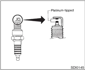
 Platinum-tipped
SDI0145
Platinum-tipped spark plugs
It is not necessary to replace the platinum-tipped spark plugs as frequently as the conventional type spark plugs since they will last much longer. Follow the maintenance log but, do not reuse them by cleaning or regapping.
Always replace with recommended platinum-tipped spark plugs.
AIR CLEANER
 SDI1446A
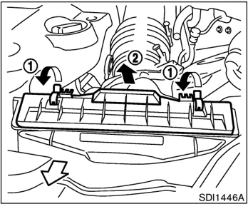
To remove the filter from the air cleaner, pull off the lock pins ① and pull the unit upward ②.
The filter element should not be cleaned and reused. Replace it according to the maintenance log shown in the "Service and Maintenance Guide". When replacing the filter, wipe the inside of the air cleaner housing and the cover with a damp cloth.
WARNING
- Operating the engine with the air cleaner removed can cause you or
8-18 Maintenance and do-it-yourself
WINDSHIELD WIPER BLADES
others to be burned. The air cleaner not only cleans the air, it stops the flame if the engine backfires. If it is not there, and the engine backfires, you could be burned. Do not drive with the air cleaner removed, and be careful when working on the engine with the air cleaner removed.
- Never pour fuel into the throttle body or attempt to start the engine with the air cleaner removed. Doing so could result in serious injury.
CAUTION
- After wiper blade replacement, return the wiper arm to its original position. Otherwise it may be damaged when the engine hood is opened.
- Make sure the wiper blades contact the glass; otherwise the arms may be damaged from wind pressure.
- Worn windshield wiper blades can damage the windshield and impair driver vision.
rinse the blade with clear water. If your wind-shield is still not clear after cleaning the blades and using the wiper, replace the blades.
CLEANING
If your windshield is not clear after using the windshield washer or if a wiper blade chatters when running, wax or other material may be on the blade or windshield.
Clean the outside of the windshield with a washer solution or a mild detergent. Your wind-shield is clean if beads do not form when rinsing with clear water.
Clean the blade by wiping it with a cloth soaked in a washer solution or a mild detergent. Then
Maintenance and do-it-yourself 8-19
 SDI1649
REPLACING Replace the wiper blades if they are worn.
- Pull the wiper arm.
- Push the release tab (A), then move the wiper blade down the wiper arm to remove ①.
- Insert the new wiper blade onto the wiper arm until a click sounds.
 SDI1730A
If necessary, clean the windshield washer nozzle (A) with a needle or small pin (B). *1: Only for passenger's side wiper arm *2: Adjustable washer nozzles
8-20 Maintenance and do-it-yourself
PARKING BRAKE AND BRAKE PEDAL
CHECKING PARKING BRAKE
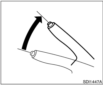
From the released position, pull the parking brake lever up slowly and firmly. If the number of clicks is out of the range listed below, see a NISSAN dealer.
- 6 - 7 clicks under pulling force of 45 lb (200 N)
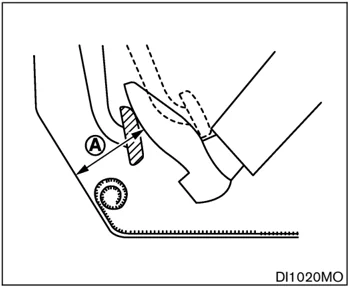
CHECKING BRAKE PEDAL
With the engine running, check the distance A between the upper surface of the pedal and the metal floor. If it is out of the range shown below, see a NISSAN dealer.
Distance A: Under depressing force of 110 lb (490 N)
| Automatic Transmission model | Manual Transmission model |
|---|---|
| 3.74 in (95 mm) or more | 3.54 in (90 mm) or more |
Self-adjusting brakes
Your vehicle is equipped with self-adjusting brakes.
The disc-type brakes self-adjust every time the brake pedal is applied.
WARNING
See a NISSAN dealer for a brake system check if the brake pedal height does not return to normal.
Brake pad wear indicators
The disc brake pads on your vehicle have audible wear indicators. When a brake pad requires replacement, it will make a high pitched scraping or screeching sound when the vehicle is in motion whether or not the brake pedal is depressed. Have the brakes checked as soon as possible if the wear indicator sound is heard.
Under some driving or climate conditions, occasional brake squeak, squeal or other noise may be heard. Occasional brake noise during light to moderate stops is normal and does not affect the function or performance of the brake system.
Proper brake inspection intervals should
Maintenance and do-it-yourself 8-21
be followed. For additional information, see the appropriate maintenance log shown in the NISSAN Service and Maintenance Guide.
BRAKE BOOSTER
Check the brake booster function as follows:
-
With the engine off, press and release the brake pedal several times. When brake pedal movement (distance of travel) remains the same from one pedal application to the next, continue on to the next step.
-
While depressing the brake pedal, start the engine. The pedal height should drop a little.
-
With the brake pedal depressed, stop the engine. Keeping the pedal depressed for about 30 seconds, the pedal height should not change.
-
Run the engine for one minute without depressing the brake pedal, then turn it off. Depress the brake pedal several times. The pedal travel distance will decrease gradually with each depression as the vacuum is released from the booster.
If the brakes do not operate properly, see a NISSAN dealer.
FUSES
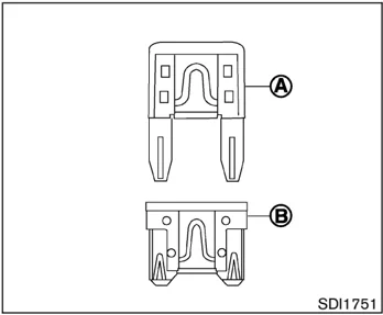
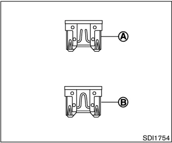
Some vehicles are equipped with engine compartment and passenger compartment fuse boxes that use only type A fuses. Other vehicles are equipped with type A fuses in the engine compartment fuse box and type B fuses in the passenger compartment fuse box.
Type A fuses are provided as spare fuses. They are stored in the passenger compartment fuse box.
Type A fuses can be installed in the engine compartment and passenger compartment fuse boxes.
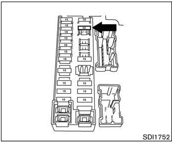
If a type A fuse is used to replace a type B fuse, the type A fuse will not be level with the fuse pocket as shown in the illustration. This will not affect the performance of the fuse. Make sure the fuse is installed in the fuse box securely.
Type B fuses cannot be installed in the underhood fuse boxes. Only use type A fuses in the underhood fuse boxes.
8-22 Maintenance and do-it-yourself
 SDI1479B
ENGINE COMPARTMENT
CAUTION
Never use a fuse of a higher or lower amperage rating than that specified on the fuse box cover. This could damage the electrical system or cause a fire.
If any electrical equipment does not operate, check for an open fuse.
-
Be sure the ignition switch and headlight switch are OFF.
-
Open the engine hood and remove the cover on the battery and the fuse/fusible link holder.
-
Remove the fuse/fusible link holder cover by pushing the tabs ① and lifting the cover ②.
-
Remove the fuse with the fuse puller. The fuse puller is located in the passenger compartment fuse box.
-
If the fuse is open A, replace it with a new fuse B. Spare fuses are stored in the passenger compartment fuse box.
-
If a new fuse also opens, have the electrical system checked and repaired by a NISSAN dealer.
 SDI1753
Fusible links
If any electrical equipment does not operate and fuses are in good condition, check the fusible links. If any of these fusible links are melted, replace only with genuine NISSAN parts.
Maintenance and do-it-yourself 8-23
SDI1962
PASSENGER COMPARTMENT
CAUTION
Never use a fuse of a higher or lower amperage rating than that specified on the fuse box cover. This could damage the electrical system or cause a fire.
If any electrical equipment does not operate, check for an open fuse.
-
Be sure the ignition switch and the headlight switch are OFF.
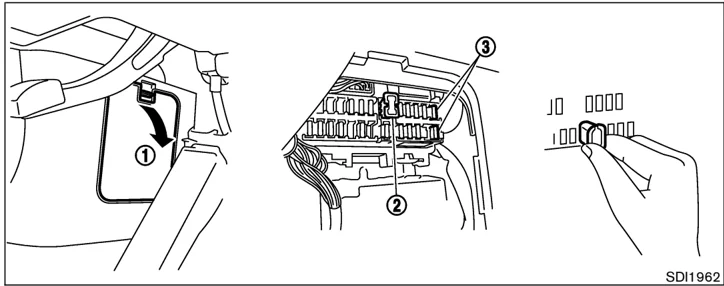
-
Open the fuse box lid ①.
-
Pinch the fuse perpendicularly with the fuse puller ② and pull it out.
-
If the fuse is open (A), replace it with a new fuse (B). Spare fuses ③ are stored in the fuse box.
-
If a new fuse also opens, have the electrical system checked and repaired by a NISSAN dealer.
8-24 Maintenance and do-it-yourself

SDI1754
KEYFOB BATTERY REPLACEMENT
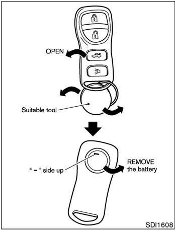
Replace the battery as follows:
- Open the lid using a suitable tool.
- Replace the battery with a new one. Recommended battery: CR2025 or equivalent
Make sure that the ⊕ side faces the bottom case. 3. Close the lid securely. 4. Push the keyfob button two or three times to check its operation.
See a NISSAN dealer if you need any assistance for replacement.
If the battery is removed for any reason other than replacement, perform step 4 above.
- Be careful not to touch the circuit board and the battery terminal.
- An improperly disposed battery can harm the environment. Always confirm local regulations for battery disposal.
- The keyfob is water-resistant; however, if it gets wet, immediately wipe it completely dry.
- When changing batteries, do not let dust or oil get on the keyfob.
FCC Notice:
Changes or modifications not expressly approved by the party responsible for compliance could void the user's authority to operate the equipment.
This device complies with Part 15 of the FCC Rules and RSS-210 of Industry Canada.
Operation is subject to the following two conditions: (1) This device may not cause harmful interference, and (2) this device must accept any interference received, including interference that may cause undesired operation of the device.
Maintenance and do-it-yourself 8-25
LIGHTS
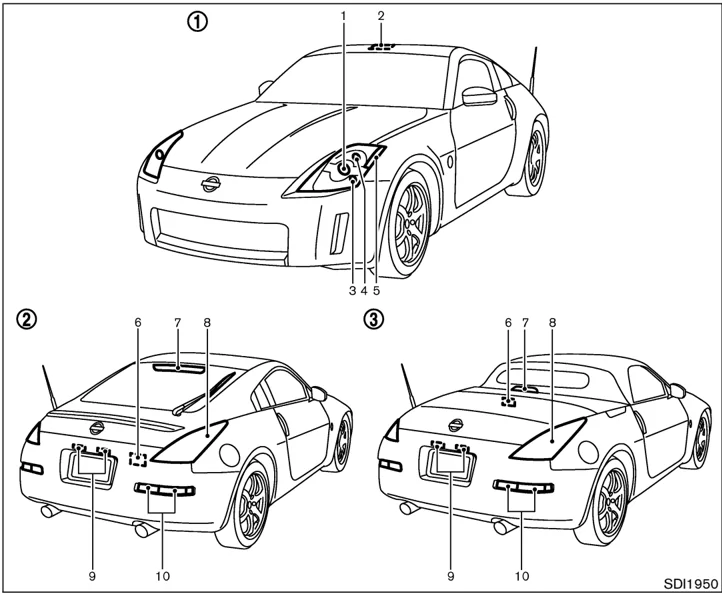
① Front view
- Headlight (low-beam, high-beam)
- Spot light
- Front park light
- Front turn signal light
- Front side marker light ② Rear view (Coupe), ③ Rear view (Roadster)
- Luggage compartment light (Coupe) or Trunk light (Roadster)
- High-mounted stop light
- Rear combination light (Side marker, Stop/Tail)
- License plate lights
- Rear combination light (Back-up, Turn signal)
8-26 Maintenance and do-it-yourself
HEADLIGHTS Replacing
If replacement is required, see a NISSAN dealer.
Xenon headlight bulb:
WARNING
HIGH VOLTAGE
When xenon headlights are on, they produce a high voltage. To prevent an electric shock, never attempt to modify or disassemble. Always have your xenon headlights replaced at a NISSAN dealer. For additional information, see “Headlight and turn signal switch” in the “2. Instruments and controls” section.
CAUTION
Use the same number and wattage as originally installed: Bulb no. (Wattage) D2S (35W) - Xenon low/high-beam
Maintenance and do-it-yourself 8-27
EXTERIOR AND INTERIOR LIGHTS
| Item | Wattage (W) | Bulb No. |
|---|---|---|
| Front turn signal light* | 28/8 | 3457NA |
| Front park light* | 5 | T10 |
| Front side marker light* | (LED) | — |
| Rear combination light (Upper) | ||
| Stop/Tail* | (LED) | — |
| Side marker* | (LED) | — |
| Rear combination light (Lower) | ||
| Back-up* | 21 | T20 |
| Turn signal* | 21 | T20 |
| License plate light (x 2) | 5 | T10 |
| High-mounted stop light* | (LED) | — |
| Spot light | 8 | — |
| Luggage compartment light (Coupe) | 5 | — |
| Trunk light (Roadster)* | 3.4 | — |
| Vanity mirror light | 1.8 | — |
| Rear floor box light* | 1.4 | — |
*: See a NISSAN dealer for replacement.
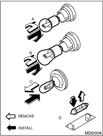
Replacement procedures
All other lights are either type A, B, C or D. When replacing a bulb, first remove the lens and/or cover.
8-28 Maintenance and do-it-yourself
10% 20% 30% 40% 50% 60% 70% 80% 90%
Interior light (Coupe)
 SDI1450A
Interior light (Roadster)
SDI1572
Interior light (Roadster) Be careful not to snap the nails A on the plastic cover when removing it.
Vanity mirror light
SDI1779
Luggage compartment light
SDI1451
Maintenance and do-it-yourself 8-29
WHEELS AND TIRES
 License plate light (2 lights)
PUSH
SDI1401A
TIRE PRESSURE
Tire pressure monitoring system (TPMS)
This vehicle is equipped with the tire pressure monitoring system (TPMS). It monitors tire pressure of all tires except the spare. When the low tire pressure warning light is lit, one or more of your tires is significantly under-inflated. The system also displays pressure of all tires (except the spare tire) on the trip computer by sending a signal from a sensor that is installed in each wheel.
The TPMS will activate only when the vehicle is driven at speeds above 16 MPH (25 km/h). Also, this system may not detect a sudden drop in tire pressure (for example a flat tire while driving).
For more details, refer to "Trip computer" and "Low tire pressure warning light" in the "2. Instruments and controls" section, "Tire pressure monitoring system (TPMS)" in the "5. Starting and driving" section, and "Flat tire" in the "6. In case of emergency" section.
Tire inflation pressure
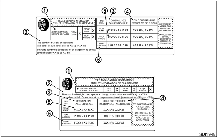
Check the tire pressures (including the spare) often and always prior to long distance trips. The recommended tire pressure specifications are shown on the Tire and Loading Information label under the "COLD TIRE PRESSURE" heading. The Tire and Loading Information label is affixed to the driver side center pillar. Tire pressures should be checked regularly because:
- Most tires naturally lose air over time.
- Tires can lose air suddenly when driven over potholes or other objects or if the vehicle strikes a curb while parking.
The tire pressures should be checked when the tires are cold. The tires are considered COLD after the vehicle has been parked for 3 or more hours, or driven less than 1 mile (1.6 km) at moderate speeds.
8-30 Maintenance and do-it-yourself
Incorrect tire pressure, including under inflation, may adversely affect tire life and vehicle handling.
WARNING
-
Improperly inflated tires can fail suddenly and cause an accident.
-
The Gross Vehicle Weight Rating (GVWR) is located on the F.M.V.S.S./C.M.V.S.S. label. The vehicle weight capacity is indicated on the Tire and Loading Information label. Do not load your vehicle beyond this capacity. Overloading your vehicle may result in reduced tire life, unsafe operating conditions due to premature tire failure, or unfavorable handling characteristics and could also lead to a serious accident. Loading beyond the specified capacity may also result in failure of other vehicle components.
-
Before taking a long trip, or whenever you heavily load your vehicle, use a tire pressure gauge to ensure that the tire pressures are at the specified level.
-
Do not drive your vehicle over 85 MPH (137 km/h) unless it is equipped with high speed rated tires. Driving faster than 85 MPH (137 km/h) may result in tire failure, loss of control and possible injury.
-
For additional information regarding tires, refer to “Important Tire Safety Information” (US) or “Tire Safety Information” (Canada) in the Warranty Information Booklet.
Maintenance and do-it-yourself 8-31
I
SDI1948
Tire and loading information label
① Seating capacity: The maximum number of occupants that can be seated in the vehicle.
② Vehicle load limit: See loading information in the “Technical and consumer information” section.
③ Original size: The size of the tires originally installed on the vehicle at the factory.
④ Cold tire pressure: Inflate the tires to this pressure when the tires are cold. Tires are considered COLD after the vehicle has been parked for 3 or more hours, or driven less than 1 mile (1.6 km) at moderate speeds. The recommended cold tire inflation is set by the manufacturer to provide the best balance of tire wear, vehicle handling, driveability, tire noise, etc., up to the vehicle’s GVWR.
⑤ Tire size — refer to “Tire labeling” later in this section.
⑥ Spare tire size or compact spare tire size (if so equipped).
8-32 Maintenance and do-it-yourself
SDI1949
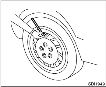
Checking the tire pressure
- Remove the valve stem cap from the tire.
- Press the pressure gauge squarely onto the valve stem. Do not press too hard or force the valve stem sideways, or air will escape. If the hissing sound of air escaping from the tire is heard while checking the pressure, reposition the gauge to eliminate this leakage.
- Remove the gauge.
- Read the tire pressure on the gauge stem and compare it to the specification shown on the Tire and Loading Information label.
- Add air to the tire as needed. If too much air is added, press the core of the valve stem briefly with the tip of the gauge stem to release pressure. Re-check the pressure and add or release air as needed.
- Install the valve stem cap.
- Check the pressure of all other tires, including the spare.
| Coupe model | Size | Cold Tire Inflation Pressure |
|---|---|---|
| Front Original Tire | 225/45R18 245/40R18 | 240 kPa (35 psi) |
| Rear Original Tire | 245/45R18 265/35R19 | 240 kPa (35 psi) |
| Spare Tire | T145/80D17 | 420 kPa (60 psi) |
| Roadster model | Size | Cold Tire Inflation Pressure |
|---|---|---|
| Front Original Tire | 225/45R18 | 240 kPa (35 psi) |
| Rear Original Tire | 245/45R18 | 240 kPa (35 psi) |
| Spare Tire | T145/80D17 | 420 kPa (60 psi) |
Maintenance and do-it-yourself 8-33
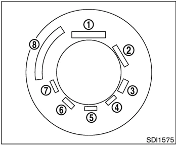
Example SDI1575
TIRE LABELING
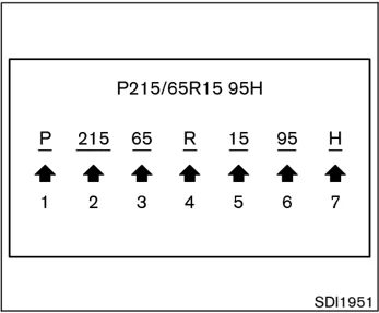
Federal law requires tire manufacturers to place standardized information on the sidewall of all tires. This information identifies and describes the fundamental characteristics of the tire and also provides the tire identification number (TIN) for safety standard certification. The TIN can be used to identify the tire in case of a recall.
Example SDI1951
① Tire size (example: P215/65R15 95H)
- P: The “P” indicates the tire is designed for passenger vehicles. (Not all tires have this information.)
- Three-digit number (215): This number gives the width in millimeters of the tire from sidewall edge to sidewall edge.
- Two-digit number (65): This number, known as the aspect ratio, gives the tire’s ratio of height to width.
- R: The “R” stands for radial.
- Two-digit number (15): This number is the wheel or rim diameter in inches.
- Two- or three-digit number (95): This number is the tire’s load index. It is a measurement of how much weight each tire can support. You may not find this information on all tires because it is not required by law.
- Tire Speed Rating. You should not drive the vehicle faster than the tire speed rating.
8-34 Maintenance and do-it-yourself
Example SDI1607
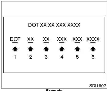
② TIN (Tire Identification Number) for a new tire (example: DOT XX XX XXX XXXX)
- DOT: Abbreviation for the “Department of Transportation”. The symbol can be placed above, below or to the left or right of the Tire Identification Number.
- Two-digit code: Manufacturer’s identification mark
- Two-digit code: Tire size
- Three-digit code: Tire type code (Optional)
- Three-digit code: Date of Manufacture
- Four numbers represent the week and year the tire was built. For example, the numbers 3103 means the 31st week of 2003. If these numbers are missing, then look on the other sidewall of the tire.
③ Tire ply composition and material The number of layers or plies of rubber-coated fabric in the tire. Tire manufacturers also must indicate the materials in the tire, which include steel, nylon, polyester, and others.
④ Maximum permissible inflation pressure This number is the greatest amount of air pressure that should be put in the tire. Do not exceed the maximum permissible inflation pressure.
⑤ Maximum load rating This number indicates the maximum load in kilograms and pounds that can be carried by the tire. When replacing the tires on the vehicle, always use a tire that has the same load rating as the factory installed tire.
⑥ Term of “tubeless” or “tube type” Indicates whether the tire requires an inner tube (“tube type”) or not (“tubeless”).
⑦ The word “radial” The word “radial” is shown if the tire has radial structure.
⑧ Manufacturer or brand name Manufacturer or brand name is shown.
Other tire-related terminology: In addition to the many terms that are defined throughout this section, Intended Outboard Sidewall is (1) the sidewall that contains a whitewall, bears white lettering or bears manufacturer, brand, and/or model name molding that is higher or deeper than the same molding on the
Maintenance and do-it-yourself 8-35
other sidewall of the tire, or (2) the outward facing sidewall of an asymmetrical tire that has a particular side that must always face outward when mounted on a vehicle.
TYPES OF TIRES
WARNING
- When changing or replacing tires, be sure all four tires are of the same type (i.e., Summer, All Season or Snow) and construction. A NISSAN dealer may be able to help you with information about tire type, size, speed rating and availability.
- Replacement tires may have a lower speed rating than the factory equipped tires, and may not match the potential maximum vehicle speed. Never exceed the maximum speed rating of the tire.
- Replacing tires with those not originally specified by NISSAN could affect the proper operation of the tire
pressure monitoring system (TPMS).
- For additional information regarding tires, refer to “Important Tire Safety Information” (US) or “Tire Safety Information” (Canada) in the Warranty Information Booklet.
All season tires
NISSAN specifies all season tires on some models to provide good performance for use all year round, including snowy and icy road conditions. All season tires are identified by ALL SEASON and/or M&S on the tire sidewall. Snow tires have better snow traction than all season tires and may be more appropriate in some areas.
Summer tires
NISSAN specifies summer tires on some models to provide superior performance on dry roads. Summer tire performance in snow and ice will be substantially reduced. Summer tires do not have the tire traction rating M&S on the tire sidewall.
If you operate your vehicle in snowy or icy conditions, NISSAN recommends the use of snow or all season tires on all four wheels.
Snow tires
If snow tires are needed, it is necessary to select tires equivalent in size and load rating to the original equipment tires. If you do not, it can adversely affect the safety and handling of your vehicle.
Generally, snow tires will have lower speed ratings than factory equipped tires and may not match the potential maximum vehicle speed. Never exceed the maximum speed rating of the tire.
If you operate your vehicle in snowy or icy conditions, NISSAN recommends the use of snow or all season tires on all four wheels.
For additional traction on icy roads, studded tires may be used. However, some provinces and states prohibit their use. Check local, state and provincial laws before installing studded tires. Skid and traction capabilities of studded snow tires, on wet or dry surfaces, may be poorer than that of non-studded snow tires.
8-36 Maintenance and do-it-yourself
TIRE CHAINS
CAUTION
Tire chains/cables cannot be installed on 265/35R19 size tires. Installation of the tire chains/cables on 265/35R19 size tires will cause damage to the vehicle. If you plan to use tire chains/cables, you should install 245/45R18 size tires on your vehicle.
Use of tire chains may be prohibited according to location. Check the local laws before installing tire chains. When installing tire chains, make sure they are of proper size for the tires on your vehicle and are installed according to the chain manufacturer’s suggestions. Use only SAE class “S” chains. Class “S” chains are used on vehicles with restricted tire to vehicle clearance. Vehicles that can use Class “S” chains are designed to meet the SAE standard minimum clearances between the tire and the closest vehicle suspension or body component required to accommodate the use of a winter traction device (tire chains or cables). The minimum clearances are determined using the factory equipped tire size. Other types may damage your vehicle. Use chain tensioners when recommended by the tire chain manufacturer to ensure a tight fit. Loose end links of the tire chain must be secured or removed to prevent the possibility of whipping action damage to the fenders or undercarriage. If possible, avoid fully loading your vehicle when using tire chains. In addition, drive at a reduced speed. Otherwise, your vehicle may be damaged and/or vehicle handling and performance may be adversely affected.
- Never install the tire chains on a T-type spare tire.
- Do not use the tire chains on dry roads.
- Tire chains must be installed only on the rear wheels and not on the front wheels.
CHANGING WHEELS AND TIRES
Tire rotation
Tires cannot be rotated in this vehicle, as front tires are different size from rear tires and the direction of wheel rotation is fixed in each tire.
A pin is on the front brake rotor to prevent the rear wheels from being installed in place of the front wheels. The spare tire can be installed in place of the front and rear wheels. When installing the spare tire in the front wheel, the hole in the spare tire wheel must be aligned with the pin on the brake rotor.
Maintenance and do-it-yourself 8-37
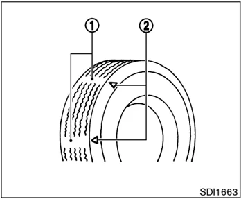
- Wear indicator
- Wear indicator location mark
Tire wear and damage
WARNING
-
Tires should be periodically inspected for wear, cracking, bulging or objects caught in the tread. If excessive wear, cracks, bulging or deep cuts are found, the tire(s) should be replaced.
-
The original tires have built-in tread wear indicators. When the wear indicators are visible, the tire(s) should be replaced.
-
Tires degrade with age and use. Have tires, including the spare, over 6 years old checked by a qualified technician because some tire damage may not be obvious. Replace the tires as necessary to prevent tire failure and possible personal injury.
-
Improper service of the spare tire may result in serious personal injury. If it is necessary to repair the spare tire, contact a NISSAN dealer.
-
For additional information regarding tires, refer to “Important Tire Safety Information” (US) or “Tire Safety Information” (Canada) in the Warranty Information Booklet.
Replacing wheels and tires
When replacing a tire, use the same size, speed rating and load carrying capacity as originally equipped. See “Specifications” in the “9. Technical and consumer information” section for recommended types and sizes of tires and wheels.
WARNING
-
The use of tires other than those recommended or the mixed use of tires of different brands, construction (bias, bias-belted or radial), or tread patterns can adversely affect the ride, braking, handling, ground clearance, body-to-tire clearance, tire chain clearance, speedometer calibration, headlight aim and bumper height. Some of these effects may lead to accidents and could result in serious personal injury.
-
If the wheels are changed for any
8-38 Maintenance and do-it-yourself
reason, always replace with wheels which have the same off-set dimension. Wheels of a different off-set could cause premature tire wear, possibly degraded vehicle handling characteristics and/or interference with the brake discs/drums. Such interference can lead to decreased braking efficiency and/or early brake pad/shoe wear.
-
When a spare tire is mounted or a wheel is replaced, tire pressure will not be indicated, the TPMS will not function and the low tire pressure warning light will flash. Contact your NISSAN dealer as soon as possible for tire replacement and/or system resetting.
-
Replacing tires with those not originally specified by NISSAN could affect the proper operation of the TPMS.
-
Do not install a deformed wheel or tire even if it has been repaired. Such wheels or tires could have structural damage and could fail without warning.
-
The use of retread tire is not recommended.
-
For additional information regarding tires, refer to "Important Tire Safety Information" (US) or "Tire Safety Information" (Canada) in the Warranty Information Booklet.
Wheel balance
Unbalanced wheels may affect vehicle handling and tire life. Even with regular use, wheels can get out of balance. Therefore, they should be balanced as required.
Wheel balance service should be performed with the wheels off the vehicle. Spin balancing the front wheels on the vehicle could lead to transmission damage.
For additional information regarding tires, refer to "Important Tire Safety Information" (US) or "Tire Safety Information" (Canada) in the Warranty Information booklet.
Care of wheels
-
Wash the wheels when washing the vehicle to maintain their appearance.
-
Clean the inner side of the wheels when the wheel is changed or the underside of the vehicle is washed.
-
Do not use abrasive cleaners when washing the wheels.
-
Inspect wheel rims regularly for dents or corrosion. Such damage may cause loss of pressure or poor seal at the tire bead.
-
NISSAN recommends that the road wheels be waxed to protect against road salt in areas where it is used during winter.
Spare tire (T-type spare tire)
Observe the following precautions if the T-type spare tire must be used, otherwise your vehicle could be damaged or involved in an accident.
CAUTION
- The T-type spare tire should be used for emergency use only. It should be replaced by the standard tire at the first opportunity.
- Drive carefully while the T-type spare tire is installed.
Maintenance and do-it-yourself 8-39
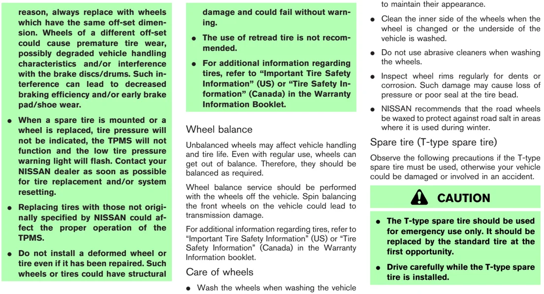
Avoid sharp turns and abrupt braking while driving.
-
Periodically check the T-type spare tire inflation pressure, and always keep it at 60 psi (420 kPa, 4.2 bar).
-
Do not drive your vehicle at speeds faster than 50 MPH (80 km/h).
-
Do not use tire chains on a T-type spare tire. Tire chains will not fit properly on the T-type spare tire and may cause damage to the vehicle.
-
Tire tread of the T-type spare tire will wear at a faster rate than the standard tire. Replace the T-type spare tire as soon as the tread wear indicators appear.
-
Because the T-type spare tire is smaller than the original tire, ground clearance is reduced. To avoid damage to the vehicle, do not drive over obstacles. Also, do not drive the vehicle through an automatic car wash since it may get caught.
-
Do not use the T-type spare tire on other vehicles.
-
Do not use more than one T-type spare tire at the same time.
-
Do not tow a trailer while the T-type spare tire is installed.
8-40 Maintenance and do-it-yourself