VEHICLE INFORMATION DISPLAY
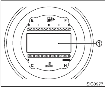
The vehicle information display ① displays the warnings and information.
INDICATORS FOR OPERATION
-
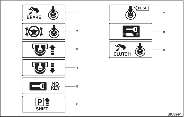
Engine start operation indicator This indicator appears when the selector lever is in the P (Park) position. This indicator means that the engine will start by pushing the ignition switch with the brake pedal depressed.
-
Steering lock release malfunction indicator This indicator appears when the steering wheel cannot be released from the LOCK position.
2-16 Instruments and controls
If this indicator appears, push the push-button ignition switch while lightly turning the steering wheel right and left.
3. Key insertion indicator
This indicator appears when the key needs to be inserted into the key port. (For example, the Intelligent Key battery is discharged.)
If this indicator appears, insert the key into the key port in the correct direction. (See “PUSH-BUTTON IGNITION SWITCH” in the “5. Starting and driving” section.)
4. Intelligent Key removal indicator
This indicator appears when the driver’s door is opened with the ignition switch in the OFF or LOCK position and the Intelligent Key placed in the key port. A key reminder chime also sounds.
If this indicator appears, remove the Intelligent Key from the key port and take it with you when leaving the vehicle.
5. NO KEY warning
This warning appears in either of the following conditions.
No Intelligent Key inside the vehicle: The warning appears when the door is closed with the Intelligent Key left outside the vehicle and the ignition switch in the ACC or ON position. Make sure that the Intelligent Key is inside the vehicle.
Unregistered Intelligent Key: The warning appears when the ignition switch is pushed from the LOCK position and the Intelligent Key cannot be recognized by the system. You cannot start the engine with an unregistered key. Use the registered Intelligent Key.
See “INTELLIGENT KEY SYSTEM” in the “3. Pre-driving checks and adjustments” section for more details.
6. SHIFT “P” warning (Automatic Transmission models)
This warning appears when the ignition switch is pushed to stop the engine with the selector lever in any position except the P (Park) position.
If this warning appears, move the selector lever to the P (Park) position or push the ignition switch to the ON position.
An inside warning chime will also sound. (See “INTELLIGENT KEY SYSTEM” in the “3. Pre-driving checks and adjustments” section.)
7. “PUSH” warning (Automatic Transmission models)
This warning appears when the selector lever is moved to the P (Park) position with the ignition switch in the ACC position after the SHIFT “P” warning appears.
To push the ignition switch to the OFF position, perform the following procedure:
SHIFT “P” warning \rightarrow (Move the selector lever to “P”) \rightarrow PUSH warning \rightarrow (Push the ignition switch \rightarrow ignition switch position is turned to ON) \rightarrow PUSH warning \rightarrow (Push the ignition switch \rightarrow ignition switch position is turned to OFF)
8. Intelligent Key battery discharge indicator
This indicator appears when the Intelligent Key battery is running out of power.
If this indicator appears, replace the battery with a new one. (See “INTELLIGENT KEY BATTERY REPLACEMENT” in the “8. Maintenance and do-it-yourself” section.)
9. Engine start operation indicator (Manual Transmission models)
This indicator means that the engine will start by pushing the ignition switch with the clutch pedal depressed.
Instruments and controls 2-17
 SIC4027
WARNINGS AND ALERTS
1. Parking brake release warning This warning appears when the vehicle speed is above 4 MPH (7 km/h) and the parking brake is applied.
2. Low fuel warning This warning appears when the fuel level in the tank is getting low. Refuel as soon as it is convenient, preferably before the fuel gauge reaches the empty (E) position.
There is a small reserve of fuel remaining in the tank when the fuel gauge reaches the empty (E) position.
3. Low washer fluid warning This warning appears when the washer tank fluid is at a low level. Add washer fluid as necessary. (See “WINDOW WASHER FLUID” in the “8. Maintenance and do-it-yourself” section.)
4. Door/rear hatch/trunk open warning (ignition switch is in the ON position) This warning appears if any of the doors and/or the rear hatch/trunk are open or not closed securely. The vehicle icon indicates which door is open on the display.
5. “Time to rest” indicator This indicator appears when the set “time to rest” indicator activates. You can set the time for up to 6 hours. (See “TRIP COMPUTER” later in this section.)
6. Low outside temperature warning This warning appears if the outside temperature is below 37°F (3°C). The warning can be set not to be displayed. (See “TRIP COMPUTER” later in this section.)
7. SynchroRev Match mode (S-MODE) warning This warning appears if a system malfunction
2-18 Instruments and controls
occurs. When the warning appears, the S-MODE function will not operate, but the manual transmission will operate normally and driving can be continued. Have the system checked by a NISSAN dealer.
INDICATORS FOR MAINTENANCE
-
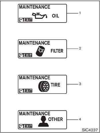
Engine oil replacement indicator This indicator appears when the set time comes for changing the engine oil. You can set or reset the distance for changing the engine oil. (See "TRIP COMPUTER" later in this section.)
-
Oil filter replacement indicator This indicator appears when the set time comes for replacing the oil filter. You can set or reset the distance for replacing the oil filter. (See "TRIP COMPUTER" later in this section.)
-
Tire replacement indicator This indicator appears when the set time comes for replacing tires. You can set or reset the distance for replacing tires. (See "TRIP COMPUTER" later in this section.)
-
"OTHER" indicator This indicator appears when the set time comes for replacing items other than the engine oil, oil filter and tires. You can set or reset the distance for replacing the items. (See "TRIP COMPUTER" later in this section.)
More maintenance reminders are also available on the center display. (See "HOW TO USE INFO BUTTON" in the "4. Center display, heater, air conditioner, audio, phone and voice recognition systems" section.)
Instruments and controls 2-19
 SIC3978
TRIP COMPUTER
Switches for the trip computer are located on the left side of the combination meter panel. To operate the trip computer, push the switches as shown above.
Ⓐ [icon] ENTER switch Ⓑ [icon] NEXT switch
When the ignition switch is pushed to the ON position, modes of the trip computer can be selected by pushing the [icon] switch Ⓐ .
Each time the [icon] switch Ⓐ is pushed, the display will change as follows:
Current fuel consumption → Average fuel consumption and speed → Elapsed time and trip odometer → Distance to empty → Outside air temperature → Setting → Warning check
 SIC3673
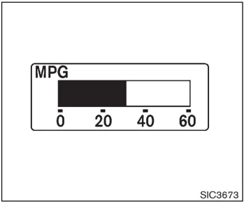
Current fuel consumption (MPG or l (liter)/100 km)
The current fuel consumption mode shows the current fuel consumption.
2-20 Instruments and controls
 SIC3674
Average fuel consumption (MPG or l (liter)/100 km) and speed (MPH or km/h)
Fuel consumption:
The average fuel consumption mode shows the average fuel consumption since the last reset. Resetting is done by pushing the ● switch Ⓑ for longer than 1 second. (The average speed is also reset at the same time.)
The display is updated every 30 seconds. At about the first 1/3 mile (500 m) after a reset, the display shows “——”.
Speed:
The average speed mode shows the average vehicle speed since the last reset. Resetting is done by pushing the ● switch Ⓑ for longer than 1 second. (The average fuel consumption is also reset at the same time.)
The display is updated every 30 seconds. The first 30 seconds after a reset, the display shows “——”.
 SIC4226
Elapsed time and trip odometer (MILES or km)
Elapsed time:
The elapsed time mode shows the time since the last reset. The displayed time can be reset by pushing the ● switch Ⓑ for longer than 1 second. (The trip odometer is also reset at the same time.)
Trip odometer:
The trip odometer mode shows the total distance the vehicle has been driven since the last reset. Resetting is done by pushing the ● switch Ⓑ for longer than 1 second. (The elapsed time is also reset at the same time.)
Instruments and controls 2-21
 SIC3676
Distance to empty (MILES or km)
The distance to empty (dte) mode provides you with an estimation of the distance that can be driven before refueling. The dte is constantly being calculated, based on the amount of fuel in the fuel tank and the actual fuel consumption.
The display is updated every 30 seconds.
The dte mode includes a low range warning feature. If the fuel level is low, the warning is displayed on the screen.
When the fuel level drops even lower, the dte display will change to "——".
-
If the amount of fuel added is small, the display just before the ignition switch is pushed to the OFF position may continue to be displayed.
-
When driving uphill or rounding curves, the fuel in the tank shifts, which may momentarily change the display.
2-22 Instruments and controls
 SIC4037
Outside air temperature (°F or °C)
The outside air temperature is displayed in °F or °C in the range of –22 to 131°F (–30 to 55°C).
The outside air temperature mode includes a low temperature warning feature. If the outside air temperature is below 37°F (3°C), the warning "ICY" is displayed on the screen.
The outside temperature sensor is located in front of the radiator. The sensor may be affected by road or engine heat, wind directions and other driving conditions. The display may differ from the actual outside temperature or the temperature displayed on various signs or billboards.
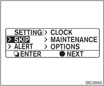
Setting Setting cannot be made while driving. A message “Setting can only be operated when stopped” is also displayed on the vehicle information display.
The ☐ switch Ⓐ and ● switch Ⓑ are used in the setting mode to select and decide a menu.
SKIP: Push the ☐ switch to move to the warning check mode. Push the ● switch Ⓑ to select other menus.
ALERT: Alert menu can be set to notify the following items.
- UPSHIFT Select this submenu to set the engine speed (RPM) of the upshift indicator. (See “Upshift indicator (if so equipped for Manual Transmission models)” in the “5. Starting and driving” section.)
- TIMER Select this submenu to specify when the “TIME TO REST” indicator activates.
- ICY Select this submenu to display the low outside temperature warning.
To return to the top page of the setting mode, select “BACK”.
CLOCK: Clock adjustment can be set on this menu.
- SETTING Adjust the time (hour and minute) of the clock on the triple meter.
- RESET Select this submenu to set the time quickly to the previous or next hour.
MAINTENANCE: The maintenance intervals of the following items can be set or reset for the reminders.
- OIL Select this submenu to set or reset the distance for changing the engine oil.
- FILTER Select this submenu to set or reset the distance for replacing the oil filter.
- TIRE Select this submenu to set or reset the distance for replacing tires.
- OTHER Select this submenu and set or reset the distance for replacing items other than the engine oil, oil filter and tires.
To return to the top page of the setting mode, select “BACK”.
OPTIONS: The 3 option menus can be set to your preference.
Instruments and controls 2-23
- LANGUAGE Select this submenu to choose English or French for display.
- UNIT Select this submenu to choose the unit from US or METRIC.
- EFFECTS Select this menu to set the dial effects described below to on or off. — The indicator needles sweep in the meters when the engine is started.
To return to the top page of the setting mode, select "BACK".
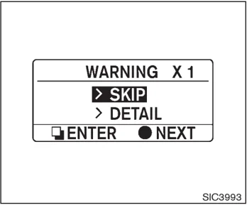
SKIP: Push the [square icon] switch Ⓐ to move to the warning check mode. Push the [circle icon] switch Ⓑ to select other menus.
DETAIL: This item is available only when a warning is displayed. Select this menu to see the details of warnings.
Warning check To see if there are any of the following warnings and corresponding details, select this menu.
- No key warning
- Low fuel warning
- Low washer fluid warning
- Parking brake release warning
- Door/rear hatch open warning
2-24 Instruments and controls
SECURITY SYSTEMS
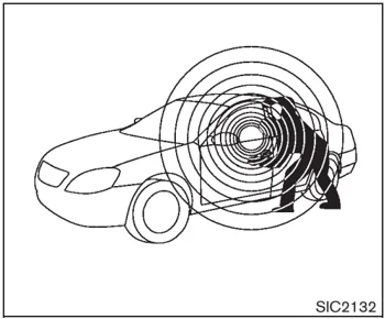
Your vehicle has two types of security systems, as follows:
- Vehicle security system
- NISSAN Vehicle Immobilizer System
The security condition will be shown by the security indicator light.
VEHICLE SECURITY SYSTEM
The vehicle security system provides visual and audio alarm signals if someone opens the doors, hood or rear hatch when the system is armed. It is not, however, a motion detection type system that activates when a vehicle is moved or when a vibration occurs.
The system helps deter vehicle theft but cannot prevent it, nor can it prevent the theft of interior or exterior vehicle components in all situations. Always secure your vehicle even if parking for a brief period. Never leave your Intelligent Key(s) in the vehicle, and always lock it when unattended. Be aware of your surroundings, and park in secure, well-lit areas whenever possible.
Many devices offering additional protection, such as component locks, identification markers, and tracking systems, are available at auto supply stores and specialty shops. Your NISSAN dealer may also offer such equipment. Check with your insurance company to see if you may be eligible for discounts for various theft protection features.
How to arm the vehicle security system
- Close all windows.
The system can be armed even if the windows are open.
-
Push the ignition switch to the OFF position.
-
Remove the Intelligent Key from the vehicle.
-
Close all doors, hood and rear hatch/trunk. Lock all doors and trunk (Roadster models). The doors can be locked with the Intelligent Key, door handle request switch, power door lock switch or mechanical key.
-
Confirm that the security indicator light comes on. The security indicator light stays
Instruments and controls 2-25
on for about 30 seconds. The vehicle security system is now pre-armed. After about 30 seconds the vehicle security system automatically shifts into the armed phase. The security light begins to flash once every approximately 3 seconds. If, during this 30-second pre-arm time period, the door is unlocked, or the ignition switch is pushed to ACC or ON, the system will not arm.
Even when the driver and/or passengers are in the vehicle, the system will activate with all doors, hood and rear hatch locked with the ignition switch in the LOCK position. When pushing the ignition switch to the ACC or ON position, the system will be released.
Vehicle security system activation The vehicle security system will give the following alarm:
- The headlights blink and the horn sounds intermittently.
- The alarm automatically turns off after approximately 1 minute. However, the alarm reactivates if the vehicle is tampered with again.
The alarm is activated by:
-
Unlocking the door or opening the rear hatch without using the button on the Intelligent Key, the door handle request switch or the mechanical key. (Even if the door is opened by releasing the door inside lock knob, the alarm will activate.)
-
Opening the hood.
How to stop an activated alarm The alarm will stop by unlocking a door by pushing the unlock button on the Intelligent Key, the door handle request switch or using the mechanical key. The alarm will not stop if the ignition switch is pushed to the ACC or ON position.
If the system does not operate as described above, have it checked by a NISSAN dealer.
NISSAN VEHICLE IMMOBILIZER SYSTEM
The NISSAN Vehicle Immobilizer System will not allow the engine to start without the use of the registered Intelligent Key. Never leave these keys in the vehicle.
Statement related to section 15 of FCC rules for NISSAN Vehicle Immobilizer System (CONT ASSY - CARD SLOT)
This device complies with part 15 of the FCC Rules and RSS-210 of Industry Canada. Operation is subject to the following two conditions;
(1) This device may not cause harmful interference, and (2) this device must accept any interference received, including interference that may cause undesired operation of the device.
CHANGES OR MODIFICATIONS NOT EXPRESSLY APPROVED BY THE PARTY RESPONSIBLE FOR COMPLIANCE COULD VOID THE USER'S AUTHORITY TO OPERATE THE EQUIPMENT.
2-26 Instruments and controls
 SIC2045
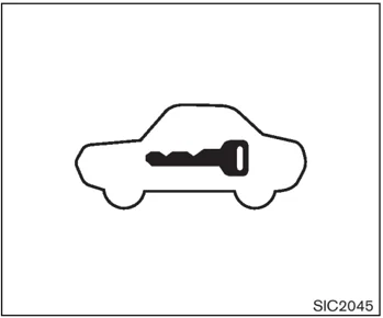
Security indicator light The security indicator light is located on the meter panel. It indicates the status of the NISSAN Vehicle Immobilizer System.
The light blinks after the ignition switch is in the LOCK, ACC or OFF position. This function indicates the security systems equipped on the vehicle are operational.
If the NISSAN Vehicle Immobilizer System is malfunctioning, this light will remain on while the ignition switch is in the ON position.
If the light still remains on and/or the engine will not start, see a NISSAN dealer for NISSAN Vehicle Immobilizer System service as soon as possible. Please bring all Intelligent Keys that you have when visiting a NISSAN dealer for service.
WINDSHIELD WIPER AND WASHER SWITCH
! WARNING
In freezing temperatures the washer solution may freeze on the windshield and obscure your vision which may lead to an accident. Warm windshield with the defroster before you wash the windshield.
! CAUTION
- Do not operate the washer continuously for more than 30 seconds.
- Do not operate the washer if the reservoir tank is empty.
- Do not fill the window washer reservoir tank with washer fluid concentrates at full strength. Some methyl alcohol based washer fluid concentrates may permanently stain the grille if spilled while filling the window washer reservoir tank.
Instruments and controls 2-27
• Pre-mix washer fluid concentrates with water to the manufacturer’s recommended levels before pouring the fluid into the window washer reservoir tank. Do not use the window washer reservoir tank to mix the washer fluid concentrate and water.
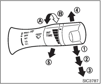
The windshield wiper and washer operates when the ignition switch is in the ON position.
Push the lever down to operate the wiper at the following speed:
① Intermittent — intermittent operation can be adjusted by turning the knob toward Ⓐ (Slower) or Ⓑ (Faster). When the speed sensing wiper interval function (for models with navigation system) is turned on, the intermittent operation speed varies in accordance with the vehicle speed. (For example, when the vehicle speed is high, the intermittent operation speed will be faster.) Note that the function is set to disabled as the factory default setting. To turn this function on and off, see “HOW TO USE SETTING BUTTON” in the “4. Center display, heater, air conditioner, audio, phone and voice recognition systems” section.
② Low — continuous low speed operation
③ High — continuous high speed operation
Push the lever up ④ to have one sweep operation of the wiper.
Pull the lever toward you ⑤ to operate the washer. Then the wiper will also operate several times.
2-28 Instruments and controls
REAR WINDOW DEFROSTER SWITCH
!
Type A SIC3980
!
Type B SIC3979
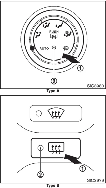
To defog/defrost the rear window glass and outside mirrors (if so equipped), start the engine and push the switch ① on. The indicator light ② will come on. Push the switch again to turn the defroster off.
It will automatically turn off in approximately 15 minutes.
CAUTION
- When cleaning the inner side of the rear window, be careful not to scratch or damage the rear window defroster.
- Do not use the rear window defroster switch while the soft top is being operated or fully opened. The heat may damage the top material and/or components (for Roadster models).
HEADLIGHT AND TURN SIGNAL SWITCH
XENON HEADLIGHTS
WARNING
HIGH VOLTAGE
- When xenon headlights are on, they produce a high voltage. To prevent an electric shock, never attempt to modify or disassemble. Always have your xenon headlights replaced at a NISSAN dealer.
- Xenon headlights provide considerably more light than conventional headlights. If they are not correctly aimed, they might temporarily blind an oncoming driver or the driver ahead of you and cause a serious accident. If headlights are not aimed correctly, immediately take your vehicle to a NISSAN dealer and have the headlights adjusted correctly.
When the xenon headlight is initially turned on, its brightness or color varies slightly. However, the color and brightness will soon stabilize.
- The life of xenon headlights will be shortened by frequent on-off operation. It is generally desirable not to turn
Instruments and controls 2-29

off the headlights for short intervals (for example, when the vehicle stops at a traffic signal). Even when the daytime running lights are active (Canada only), the xenon headlights do not turn on. This way the life of the xenon headlights is not reduced.
- If the xenon headlight bulb is close to burning out, the brightness will drastically decrease, the light will start blinking, or the color of the light will become reddish. If one or more of the above signs appear, contact a NISSAN dealer.
SIC3994
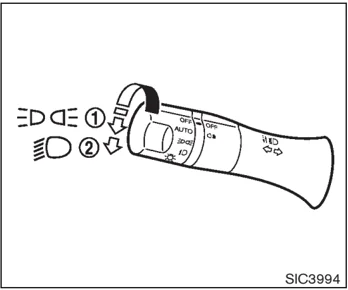
HEADLIGHT SWITCH
Lighting
① Turn the switch to the position: The front park, side marker, tail, license plate and instrument lights will come on.
② Turn the switch to the position: Headlights will come on and all the other lights remain on.
Black plate (90,1)
SIC3995
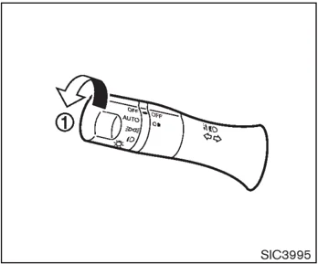
Autolight system
The autolight system allows the headlights to be set so they turn on and off automatically.
To set the autolight system:
-
Make sure the headlight switch is in the AUTO position ①.
-
Push the ignition switch to the ON position.
-
The autolight system automatically turns the headlights on and off.
To turn the autolight system off, turn the switch to the OFF, or position.
The autolight system can turn on the headlights
2-30 Instruments and controls
automatically when it is dark and turn off the headlights when it is light.
If the ignition switch is pushed to the OFF position and one of the doors is opened and this condition is continued, the headlights remain on for 5 minutes.
Automatic headlights off delay:
You can keep the headlights on for up to 180 seconds after you push the ignition switch to OFF and open any door then close all the doors.
You can adjust the period of the automatic headlights off delay from 0 seconds (OFF) to 180 seconds. The factory default setting is 45 seconds.
For automatic headlights off delay setting, see "Light Off Delay" in the "4. Center display, heater, air conditioner, audio, phone and voice recognition systems" section.
 Be sure not to put anything on top of the photo sensor Ⓐ located on the top of the instrument panel. The photo sensor controls the autolight; if it is covered, the photo sensor reacts as if it is dark and the headlights will illuminate.
 Headlight beam select
① To select the low beam, put the lever in the neutral position as shown.
② To select the high beam, push the lever forward while the switch is in the \equiv position. Pull it back to select the low beam.
③ Pulling the lever toward you will flash the headlight high beam even when the headlight switch is in the OFF position.
Battery saver system
A chime will sound when the driver side door is opened with the light switch in the \equiv or [headlight icon] position and the ignition switch in the ACC, OFF or LOCK position.
Instruments and controls 2-31
When the headlight switch is in the or position while the ignition switch is in the ON position, the lights will automatically turn off 5 minutes after the ignition switch has been pushed to the OFF position.
When the headlight switch remains in the or position after the lights automatically turn off, the lights will turn on when the ignition switch is pushed to the ON position.
CAUTION
- When you turn on the headlight switch again after the lights automatically turn off, the lights will not turn off automatically. Be sure to turn the light switch to the OFF position when you leave the vehicle for extended periods of time, otherwise the battery will be discharged.
- Never leave the light switch on when the engine is not running for extended periods of time even if the headlights turn off automatically.
Daytime running light system (Canada only) The daytime running lights automatically illuminate when the engine is started with the parking brake released. The daytime running lights operate with the headlight switch in the OFF position or in the position. Turn the headlight switch to the position for full illumination when driving at night.
If the parking brake is applied before the engine is started, the daytime running lights do not illuminate. The daytime running lights illuminate once the parking brake is released. The daytime running lights will remain on until the ignition switch is pushed to the OFF position.
WARNING
It is necessary at dusk to turn on your headlights. Failure to do so could cause an accident injuring yourself and others.

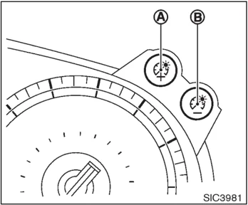
SIC3981
Instrument brightness control The instrument brightness control operates when the headlight control switch is in the , or AUTO position (with the autolights activated).
Push the upper A or lower B switch to brighten or dim the instrument panel lights when driving at night.
2-32 Instruments and controls
 SIC3997
TURN SIGNAL SWITCH
① Turn signal Move the lever up or down to signal the turning direction. When the turn is completed, the turn signals cancel automatically.
② Lane change signal To indicate a lane change, move the lever up or down to the point where lights begin flashing.
 SIC4066
FOG LIGHT SWITCH (if so equipped)
To turn on the rear fog light, turn the headlight switch to the position, then turn the fog light switch to the position.
The switch returns to the OFF position automatically, and the rear fog light will illuminate.
Make sure the indicator light on the instrument panel illuminates.
To turn off the rear fog light, turn the fog light switch to the position again.
Make sure the indicator light on the instrument panel turns off.
HAZARD WARNING FLASHER SWITCH
 SIC2574
Push the switch on to warn other drivers when you must stop or park under emergency conditions. All turn signal lights will flash.
WARNING
- If stopping for an emergency, be sure to move the vehicle well off the road.
- Do not use the hazard warning flashers while moving on the highway unless unusual circumstances force you to drive so slowly that your vehicle might become a hazard to other traffic.
Instruments and controls 2-33
HORN
- Turn signals do not work when the hazard warning flasher lights are on.
The flasher can be actuated with the ignition switch in any position.
Some state laws may prohibit the use of the hazard warning flasher switch while driving.
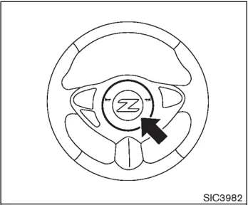
To sound the horn, push the center pad area of the steering wheel.
WARNING Do not disassemble the horn. Doing so could affect proper operation of the supplemental front air bag system. Tampering with the supplemental front air bag system may result in serious personal injury.
HEATED SEATS (if so equipped)
WARNING Do not use or allow occupants to use the seat heater if you or the occupants cannot monitor elevated seat temperatures or have an inability to feel pain in those body parts in contact with the seat. Use of the seat heater by such people could result in serious injury.
CAUTION
- The battery could run down if the seat heater is operated while the engine is not running.
- Do not use the seat heater for extended periods or when no one is using the seat.
- Do not put anything on the seat which insulates heat, such as a blanket, cushion, seat cover, etc. Otherwise, the seat may become overheated.
- Do not place anything hard or heavy on the seat or pierce it with a pin or similar object. This may result in damage to the heater.
2-34 Instruments and controls
- Any liquid spilled on the heated seat should be removed immediately with a dry cloth.
- When cleaning the seat, never use gasoline, thinner, or any similar materials.
- If any abnormalities are found or the heated seat does not operate, turn the switch off and have the system checked by a NISSAN dealer.
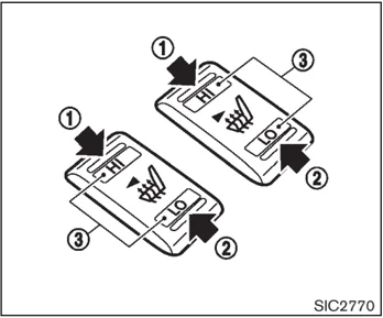
The front seats are warmed by built-in heaters. The switches located on the center console can be operated independently of each other.
- Start the engine.
- Select the desired heat range.
- For high heat, push the HI side of the switch ① .
- For low heat, push the LO side of the switch ② .
- The indicator light ③ will illuminate when the heater is on.
- To turn off the heater, return the switch to the level position. Make sure that the indicator light turns off.
The heater is controlled by a thermostat, automatically turning the heater on and off. The indicator light will remain on as long as the switch is on.
When the vehicle's interior is warmed, or before you leave the vehicle, be sure to turn off the switch.
Instruments and controls 2-35
CLIMATE CONTROLLED SEATS (if so equipped)
 SIC2771
The climate controlled seat warms up or cools down the front seats by blowing warm or cool air from the surface of the seat. The switches located on the center console can be operated independently of each other.
The surface temperature of the climate controlled seats is automatically controlled at an optimum temperature. However, adjust the temperature using the control knob if the seats are too hot or cold.
- Start the engine.
- Turn the control knob Ⓐ to the heat side ① or to the cool side ②. The indicator light Ⓑ on the control knob will illuminate.
- Adjust the desired amount of the air using the control knob Ⓐ.
- When the vehicle's interior is warmed or cooled, and/or before you leave the vehicle, be sure to turn the control knob to the OFF position (center). The indicator light Ⓑ on the control knob goes off at the OFF position.
To check the air filter for the climate controlled seat, contact a NISSAN dealer.
CAUTION
-
Do not place objects in front of the intake inlets located behind and under the front seat. Doing so could cause improper operation or interruption of the operation.
-
The battery could run down if the climate controlled seat is operated while the engine is not running.
-
Do not use the climate controlled seat for extended periods or when no one is using the seat.
-
Do not put anything on the seat which insulates heat, such as a blanket, cushion, seat cover, etc. Otherwise, the seat may become overheated.
-
Do not place anything hard or heavy on the seat or pierce it with a pin or similar object. This may result in damage to the climate controlled seat.
-
Any liquid spilled on the seat should be removed immediately with a dry cloth.
-
The climate controlled seat has air filters. Do not operate the climate controlled seat without the air filters. This may result in damage to the system.
-
When cleaning the seat, never use gasoline, thinner, or any similar materials.
-
If any malfunctions are found or the climate controlled seat does not operate, turn the switch off and have the system checked by a NISSAN dealer.
2-36 Instruments and controls
VEHICLE DYNAMIC CONTROL (VDC) OFF SWITCH
SIC4004
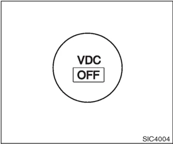
The vehicle should be driven with the Vehicle Dynamic Control (VDC) system on for most driving conditions.
If the vehicle is stuck in mud or snow, the VDC system reduces the engine output to reduce wheel spin. The engine speed will be reduced even if the accelerator is depressed to the floor. If maximum engine power is needed to free a stuck vehicle, turn the VDC system off.
To turn off the VDC system, push the VDC OFF switch. The indicator will illuminate.
Push the VDC OFF switch again or restart the engine to turn on the system. (See "VEHICLE DYNAMIC CONTROL (VDC) SYSTEM" in the "5. Starting and driving" section.)
POWER OUTLET
The power outlet is located in the center console and on the lower glove box.
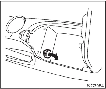
Center console
SIC3984
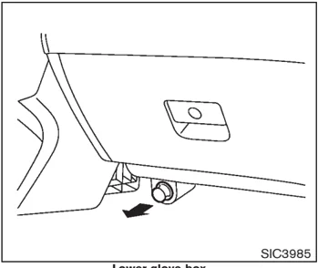
Lower glove box
SIC3985
CAUTION
- The outlet and plug may be hot during or immediately after use.
- Do not use with accessories that exceed a 12 volt, 120W (10A) power draw. Do not use double adapters or more than one electrical accessory.
- Use power outlet with the engine running to avoid discharging the vehicle battery.
- Avoid using power outlet when the air conditioner, headlights or rear window defroster is on.
- This power outlet is not designed for use with a cigarette lighter unit.
- Push the plug in as far as it will go. If good contact is not made, the plug may overheat or the internal temperature fuse may blow.
- Before inserting or disconnecting a plug, be sure the electrical accessory being used is turned OFF.
- When not in use, be sure to close the cap. Do not allow water to
Instruments and controls 2-37
STORAGE
contact the outlet.
SIC3987
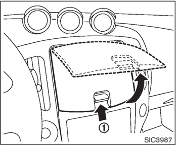
INSTRUMENT POCKET (except for navigation system equipped models) To open the lid, push the knob up ① . To close, push the lid down.
WARNING
Keep the pocket lid closed while driving to help prevent injury in an accident or a sudden stop.
CUP HOLDERS
CAUTION
- Avoid abrupt starting and braking when the cup holder is being used to prevent spilling the drink. If the liquid is hot, it can scald you or your passenger.
- Use only soft cups in the cup holder. Hard objects can injure you in an accident.
2-38 Instruments and controls
 SIC4071
A cup holder is located on the center console.
 SIC3988
Soft bottle holder
CAUTION
- Do not use bottle holder for any other objects that could be thrown about in the vehicle and possibly injure people during sudden braking or an accident.
- Do not use bottle holder for open liquid containers.
 SIC3999
GLOVE BOX
WARNING
Keep glove box lid closed while driving to help prevent injury in an accident or a sudden stop.
To open the glove box, pull the handle ① . To close, push the lid in until the lock latches. To lock ② /unlock ③ the glove box, use the mechanical key. For the mechanical key usage, see “KEYS” in the “3. Pre-driving checks and adjustments” section.
Instruments and controls 2-39
 SIC4070
CONSOLE BOX
To open the console box, push the button ① and pull up the lid.
To close, push the lid down until latched.
 SIC3989
REAR PARCEL BOX
The rear parcel box is located behind the right-side seat.
To open the rear parcel box, pull the upper part of the lid to position ① or ② .
To remove the rear parcel box, pull the lid to position ③ with a greater force until it unlatches. And then, pull the rear parcel box to direction ④ .
To install, make sure the two hinges of the rear parcel box engaged with the holders, then perform the steps above in the reverse order.
⚠ WARNING
Keep the rear parcel box lid closed while driving to help prevent injury in an accident or a sudden stop.
2-40 Instruments and controls
 SIC4026
CARGO COVER (if so equipped)
The cargo cover keeps the contents in the cargo area hidden from the outside.
To use the cargo cover, pull it out and hang both sides on the hooks ① located on the inside of the rear hatch.
 SIC3990
To remove the cargo cover unit, stow the cover and pull the holder ② to the opposite side.
WARNING
-
Never put anything on the cargo cover, no matter how small. Any object on it could cause an injury in an accident or sudden stop.
-
Do not leave the cargo cover in the vehicle with it disengaged from the holder.
-
Properly secure all cargo with ropes or straps to help prevent it from sliding or shifting. Do not place cargo higher than the seatbacks. In a sudden stop or collision, unsecured cargo could cause personal injury.
-
Your child could be seriously injured or killed in a collision if the child restraint top tether strap is damaged. — If the cargo cover contacts the top tether strap when it is attached to the top tether anchor, remove the cargo cover from the vehicle or secure it on the cargo floor below its attachment location. If the cargo cover is not removed, it may damage the top tether strap during a collision. — Do not allow cargo to contact the top tether strap when it is attached to the top tether anchor. Properly secure the cargo so it does not contact the top tether strap. Cargo that is not properly secured or that contacts the top tether strap may damage the top tether strap during a collision.
Instruments and controls 2-41
WINDOWS
POWER WINDOWS
WARNING
- Make sure that all passengers have their hands, etc. inside the vehicle while it is in motion and before closing the windows. Use the window lock switch to prevent unexpected use of the power windows.
- Do not leave children unattended inside the vehicle. They could unknowingly activate switches or controls and become trapped in the window. Unattended children could become involved in serious accidents.
The power windows operate when the ignition switch is in the ON position or for about 45 seconds after the ignition switch is pushed to the OFF position. If the driver's or front passenger's door is opened during this period of about 45 seconds, power to the windows is canceled.
The power window switches will be deactivated during soft top operation (Roadster models).

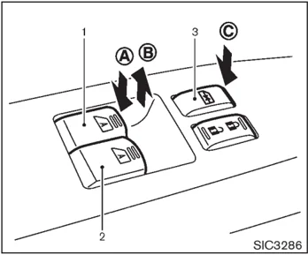
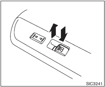
Main power window switch (driver's side)
- Driver side window
- Front passenger side window
- Window lock button
To open or close the window, push down Ⓐ or pull up Ⓑ the switch and hold it. The main switch (driver side switches) will open or close all the windows.
Locking passengers' window
When the lock button Ⓒ is pushed in, only the driver side window can be opened or closed. Push it in again to cancel.
Passenger side power window switch
The passenger side switch will open or close only the corresponding window. To open or close the window, push down or pull up the switch and hold it.
2-42 Instruments and controls
 SIC3288
Automatic operation
To fully open or close the window, completely push down or pull up the switch and release it; it need not be held. The window will automatically open or close all the way. To stop the window, just push or lift the switch in the opposite direction.
A light push or pull on the switch will cause the window to open or close until the switch is released.
Auto reverse function
WARNING
There are some small distances immediately before the closed position which cannot be detected. Make sure that all passengers have their hands, etc., inside the vehicle before closing the window.
If the control unit detects something caught in the window as it is closing, the window will be immediately lowered.
The auto reverse function can be activated when the window is closed by automatic operation when the ignition switch is in the ON position or for 45 seconds after the ignition switch is pushed to the OFF position.
Depending on the environment or driving conditions, the auto reverse function may be activated if an impact or load similar to something being caught in the window occurs.
Automatic window lowering (Roadster models)
When the soft top operating switch is pressed, the power windows will automatically be lowered completely. The windows do not rise automatically after the soft top open/close operation is completed. Use the power window switches to raise them.
Automatic adjusting function
CAUTION
When the battery cable is removed from the battery terminal, do not close either of the front doors. The automatic window adjusting function will not work and the side roof panel may be damaged.
The power window has an automatic adjusting function. When the door is being opened, the window is automatically lowered slightly to avoid contact between the window and the side roof panel. When the door is closed, the window is automatically raised slightly.
While the automatic adjusting function does not work, the window will be controlled as follows:
- When the door is opened, the window lowers for approximately 2 seconds.
Instruments and controls 2-43
INTERIOR LIGHTS
- While the door is open, the window cannot be raised.
If the windows do not close automatically
If the power window automatic function (closing only) does not operate properly, perform the following procedure to initialize the power window system.
- Push the ignition switch to the ON position.
- Close the door and soft top (Roadster models).
- Open the window completely by operating the power window switch.
- Pull the power window switch and hold it to close the window, and then hold the switch more than 3 seconds after the window is closed completely.
- Release the power window switch. Operate the window by the automatic function to confirm the initialization is complete.
- Perform steps 2 through 5 above for other windows.
If the power window automatic function does not operate properly after performing the procedure above, have your vehicle checked by a NISSAN dealer.
SIC4238
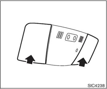
MAP LIGHTS
Push the button as illustrated to turn the light on or off.
SIC4239
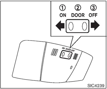
INTERIOR LIGHT CONTROL SWITCH
The interior light control switch has three positions: ON, DOOR and OFF.
ON position
When the switch is in the ON position ① the map lights will illuminate.
DOOR position
When the switch is in the DOOR position ②, the map lights will illuminate under the following conditions:
- ignition switch is switched to the OFF or LOCK position — remain on for about 15 seconds.
2-44 Instruments and controls
- doors are unlocked by pushing the UNLOCK button on the Intelligent Key or door handle request switch with the ignition switch in the LOCK position — remain on for about 15 seconds.
- any door is opened and then closed with the ignition switch in the LOCK position — remain on for about 15 seconds.
- any door is opened with the ignition switch in the ACC or ON position — remain on while the door is opened. When the door is closed, the lights go off.
The lights will also turn off after 30 minutes when the lights remain illuminated after the ignition switch has been pushed to the OFF or LOCK position to prevent the battery from becoming discharged.
When the auto interior illumination is set to the OFF position (see “VEHICLE INFORMATION AND SETTINGS (models with navigation system)” in the “4. Center display, heater, air conditioner, audio, phone and voice recognition systems” section), the lights will illuminate under the following condition:
- any door is opened with the ignition switch in any position — remain on while the door is opened. When the door is closed, the lights go off.
OFF position When the switch is in the OFF position ③, the lights will not illuminate, regardless of the condition.
CAUTION
Do not use for extended periods of time with the engine stopped. This could result in a discharged battery.
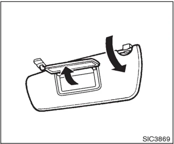
VANITY MIRROR LIGHTS
SIC3869
The light on the vanity mirror will turn on when the cover on the vanity mirror is opened.
When the cover is closed, the light will turn off.
The lights will also turn off after 30 minutes when the lights remain illuminated to prevent the battery from becoming discharged.
Instruments and controls 2-45
CARGO AREA COURTESY LIGHT (Roadster models)
The light illuminates simultaneously with the map light. See “INTERIOR LIGHTS” earlier in this section.
CARGO LIGHT (Coupe models)
The light illuminates when the rear hatch is opened. When the rear hatch is closed, the light will turn off.
The light will also turn off after 30 minutes when the light remains illuminated after the ignition switch has been pushed to the OFF or LOCK position to prevent the battery from becoming discharged.
TRUNK LIGHT (Roadster models)
The light illuminates when the trunk lid is opened. When the trunk lid is closed, the light turns off.
2-46 Instruments and controls
HomeLink® UNIVERSAL TRANSCEIVER (if so equipped)
HomeLink® Universal Transceiver provides a convenient way to consolidate the functions of up to three individual hand-held transmitters into one built-in device.
HomeLink® Universal Transceiver:
- Will operate most Radio Frequency (RF) devices such as garage doors, gates, home and office lighting, entry door locks and security systems.
- Is powered by your vehicle's battery. No separate batteries are required. If the vehicle's battery is discharged or is disconnected, HomeLink® will retain all programming.
Once HomeLink® Universal Transceiver is programmed, retain the original transmitter for future programming procedures (Example: new vehicle purchases). Upon sale of the vehicle, the programmed HomeLink® Universal Transceiver buttons should be erased for security purposes. For additional information, see "PROGRAMMING HomeLink®" later in this section.
WARNING
-
Do not use HomeLink® Universal Transceiver with any garage door opener that lacks safety stop and reverse features as required by federal safety standards. (These standards became effective for opener models manufactured after April 1, 1982.) A garage door opener which cannot detect an object in the path of a closing garage door and then automatically stop and reverse, does not meet current federal safety standards. Using a garage door opener without these features increases the risk of serious injury or death.
-
During programming procedure, your garage door or security gate may open or close. Make sure that people and objects are clear of the garage door, gate, etc. that you are programming.
-
Your vehicle's engine should be turned off while programming HomeLink® Universal Transceiver.
PROGRAMMING HomeLink®
To program your HomeLink® Transceiver to operate a garage door, gate, or entry door opener, home or office lighting, you need to be at the same location as the device. Note: Garage door openers (manufactured after 1996) have "rolling code protection". To program a garage door opener equipped with "rolling code protection"; you will need to use a ladder to get up to the garage door opener motor to be able to access the "smart or learn" program button.
Instruments and controls 2-47
 SIC3612
-
To begin, push and hold the 2 outer Home-Link® buttons (to clear the memory) until the indicator light Ⓐ blinks (after 20 seconds). Release both buttons.
-
Position the end of the hand-held transmitter 1 to 3 in (20 to 70 mm) away from the HomeLink® surface.
 SIC3613
-
Using both hands, simultaneously push and hold both the HomeLink® button you want to program and the hand-held transmitter button. DO NOT release the buttons until step 4 has been completed.
-
Hold down both buttons until the indicator light on HomeLink® flashes, changing from a "slow blink" to a "rapid blink". This could take up to 90 seconds. When the indicator light blinks rapidly, both buttons may be released. The rapidly flashing light indicates successful programming. To activate the garage door or other programmed device, push and hold the programmed HomeLink® button - releasing when the device begins to activate.
-
If the indicator light on HomeLink® blinks rapidly for two seconds and then turns solid, HomeLink® has picked up a "rolling code" garage door opener signal. You will need to proceed with the next steps to train Home-Link®, completing the programming may require a ladder and another person for convenience.
-
Push and release the program button located on the garage door opener's motor to activate the "training mode". This button is usually located near the antenna wire that hangs down from the motor. If the wire originates from under a light lens, you will need to remove the lens to access the training button.
NOTE: Once you have pushed and released the training button on the garage door opener's motor and the "training light" is lit, you have 30 seconds in which to perform step 7. For convenience, use the help of a second person to assist when performing this step.
- Quickly (within 30 seconds of pushing and releasing the garage door opener training button) and firmly push and release the HomeLink® button you have just pro-grammed. Push and release the HomeLink®
2-48 Instruments and controls
button up to three times to complete the training.
- Your HomeLink® button should now be programmed. To program the remaining HomeLink® buttons for additional door or gate openers, follow steps 2 through 8 only.
NOTE: Do not repeat step 1 unless you want to “clear” all previously programmed Home-Link® buttons.
If you have any questions or are having difficulty programming your HomeLink® buttons, please refer to the HomeLink® web site at: www. homelink.com or call 1-800-355-3515.
PROGRAMMING HomeLink® FOR CA-NADIAN CUSTOMERS
Prior to 1992, D.O.C. regulations required hand-held transmitters to stop transmitting after 2 seconds. To program your hand-held trans-mitter to HomeLink®, continue to push and hold the HomeLink® button (note steps 2 through 4 under “Programming HomeLink®”) while you push and re-push (“cycle”) your hand-held transmitter every 2 seconds until the indicator light flashes rapidly (indicating successful pro-gramming).
NOTE: If programming a garage door opener, etc., it is advised to unplug the device during the “cycling” process to prevent possible damage to the garage door opener com-ponents.
OPERATING THE HomeLink® UNIVER-SAL TRANSCEIVER
HomeLink® Universal Transceiver (once pro-grammed) may now be used to activate the garage door, etc. To operate, simply push the appropriate programmed HomeLink® Universal Transceiver button. The red indicator light will illuminate while the signal is being transmitted.
PROGRAMMING TROUBLE-DIAGNO-SIS
If HomeLink® does not quickly learn the hand-held transmitter information:
- replace the hand-held transmitter batteries with new batteries.
- position the hand-held transmitter with its battery area facing away from the Home-Link® surface.
- push and hold both the HomeLink® and hand-held transmitter buttons without inter-ruption.
- position the hand-held transmitter 2 to 5 in (50 to 127 mm) away from the HomeLink® surface. Hold the transmitter in that position for up to 15 seconds. If HomeLink® is not programmed within that time, try holding the transmitter in another position - keeping the indicator light in view at all times.
If you continue to have programming difficulties, please contact the NISSAN Consumer Affairs Department. The phone numbers are located in the Foreword of this Owner’s Manual.
CLEARING THE PROGRAMMED IN-FORMATION
Individual buttons cannot be cleared, however to clear all programming, push and hold the two outside buttons and release when the indicator light begins to flash (in approximately 20 seconds).
REPROGRAMMING A SINGLE Home-Link® BUTTON
To reprogram a HomeLink® Universal Transcei-ver button, complete the following.
- Push and hold the desired HomeLink® button. Do not release the button until step 4 has been completed.
- When the indicator light begins to flash slowly (after 20 seconds), position the hand-held transmitter 2 to 5 in (50 to 127
Instruments and controls 2-49
mm) away from the HomeLink® surface.
-
Push and hold the hand-held transmitter button.
-
The HomeLink® indicator light will flash, first slowly and then rapidly. When the indicator light begins to flash rapidly, release both buttons.
The HomeLink® Universal Transceiver button has now been reprogrammed. The new device can be activated by pushing the HomeLink® button that was just programmed. This procedure will not affect any other programmed HomeLink® buttons.
IF YOUR VEHICLE IS STOLEN
If your vehicle is stolen, you should change the codes of any non-rolling code device that has been programmed into HomeLink®. Consult the Owner's Manual of each device or call the manufacturer or dealer of those devices for additional information.
When your vehicle is recovered, you will need to reprogram the HomeLink® Universal Transceiver with your new transmitter information.
FCC Notice:
This device complies with FCC rules part 15. Operation is subject to the following two conditions: (1) This device may not cause harmful interference and (2) This device must accept any interference that may be received, including interference that may cause undesired operation.
The transmitter has been tested and complies with FCC and DOC/MDC rules. Changes or modifications not expressly approved by the party responsible for compliance could void the user's authority to operate the device.
DOC: ISTC 1763K1313
FCC I.D.: CB2V67690
2-50 Instruments and controls