SECTION 1 - 9
OPERATION OF INSTRUMENTS AND CONTROLS
Air conditioning system
- Controls . . . . . . . . . . . . . . . . . . . . . . . . . . . . . . . . . . . . . . . . . . . . . . . . . . . . . . . . . . . . . . . . . . . . . . . . . . . . . . . . . . . . . . . . . . . . . . . . . . . . . . . . . . . . . . . . . . . . . . . . . . . . . . . . . . . . . . . . . . . . . . . . . . . . . . . . . . . . . . . . . . . . . . . . . . . . . . . . . . . . . . . . . . . . . . . . . . . . ........ 168
- Air flow selector settings . . . . . . . . . . . . . . . . . . . . . . . . . . . . . . . . . . . . . . . . . . . . . . . . . . . . . . . . . . . . . . . . . . . . . . . . . . . . . . . . . . . . . . . . . . . . . . . . . . . . . . . . . . . . . . . ........ 171
- Operating tips . . . . . . . . . . . . . . . . . . . . . . . . . . . . . . . . . . . . . . . . . . . . . . . . . . . . . . . . . . . . . . . . . . . . . . . . . . . . . . . . . . . . . . . . . . . . . . . . . . . . . . . . . . . . . . . . . . . ........

Controls
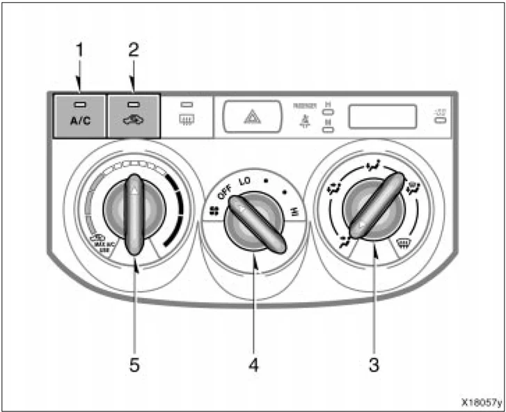
- “A/C” button (on some models)
- Air intake selector
- Air flow selector
- Fan speed selector
- Temperature selector
X18057y
168
Fan speed selector Turn the knob to adjust the fan speed—to the right to increase, to the left to decrease.
Temperature selector Turn the knob to adjust the temperature—to the right to warm, to the left to cool.
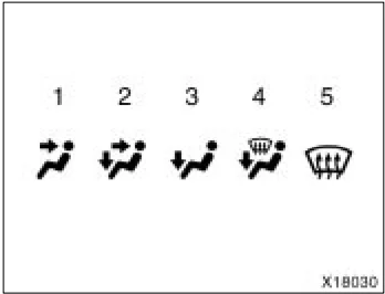
Air flow selector Turn the knob to select the vents used for air flow.
- Panel—Air flows mainly from the instrument panel vents.
- Bi-level—Air flows from both the floor vents and the instrument panel vents.
- Floor—Air flows mainly from the floor vents.
- Floor/Windshield—Air flows mainly from the floor vents and windshield vents.
Turning the air flow selector to the floor/windshield position turns on the defogging function with the purpose of clearing the front view.
This position allows the air intake to select FRESH automatically. This is to clean up the front view more quickly. If you want to return the setting to RECIRCULATE mode, press the air intake selector button once again.
Vehicles with “A/C” button— Press the “A/C” button for dehumidified heating or cooling. This setting clears the front view more quickly.
- Windshield—Air flows mainly from the windshield vents.
Turning the air flow selector to the windshield position turns on the defogging function with the purpose of clearing the front view.
This position allows the air intake to select FRESH automatically. This is to clean up the front view more quickly. If you want to return the setting to RECIRCULATE mode, press the air intake selector button once again.
Vehicles with “A/C” button— Press the “A/C” button for dehumidified heating or cooling. This setting clears the front view more quickly.
169
For details about air flow selector settings, see “Air flow selector settings” described below.
X18040
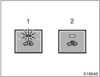
Air intake selector Press the button to select the air source.
- RECIRCULATE—Recirculates the air inside the vehicle.
- FRESH—Draws outside air into the system.
To prevent fogging up of the windshield, the air intake mode may change automatically to FRESH depending on the condition of the air conditioning system.
“A/C” button (on some models) To turn on the air conditioning, press the “A/C” button. The “A/C” button indicator will come on. To turn the air conditioning off, press the button again.
If the “A/C” button indicator flashes, there is a problem in the air conditioning system and the air conditioning automatically shuts off. If this happens, take your vehicle to a Toyota dealer for service.
170
Air flow selector settings
 : On some models
X18047y
Operating tips
● To cool off your Toyota after it has been parked in the hot sun, drive with the windows open for a few minutes. This vents the hot air, allowing the air conditioning to cool the interior more quickly.
● Make sure the air intake grilles in front of the windshield are not blocked (by leaves or snow, for example).
● On humid days, do not blow cold air on the windshield. The windshield could fog up because of the difference in air temperature on the inside and outside of the windshield.
● Keep the area under the front seats clear to allow air to circulate throughout the vehicle.
● On cold days, set the fan speed to high for a minute to help clear the intake ducts of snow or moisture. This can reduce the amount of fogging on the windows.
● When driving on dusty roads, close all windows. If dust thrown up by the vehicle is still drawn into the vehicle after closing the windows, it is recommended that the air intake selector be set to FRESH and the fan speed selector to any setting except "OFF".
171
● If following another vehicle on a dusty road, or driving in windy and dusty conditions, it is recommended that the air intake selector be temporarily set to RECIRCULATE, which will close off the outside passage and prevent outside air and dust from entering the vehicle interior.
Heating For best results, set controls to:
Fan speed—Any setting except “OFF” Temperature—Towards WARM (red zone) Air intake—FRESH (outside air) Air flow—FLOOR Air conditioning—OFF
● For quick heating, select recirculated air for a few minutes. To keep the windows from fogging, select fresh after the vehicle interior has been warmed.
● Press the “A/C” button on for dehumidified heating.
● Choose floor/windshield air flow to heat the vehicle interior while defrosting or defogging the windshield.
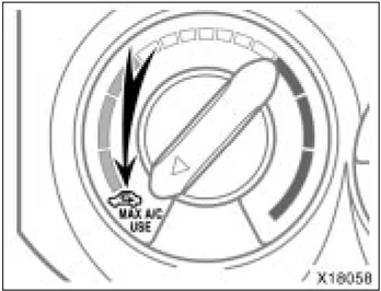
Air conditioning For best results, set controls to:
Fan speed—Any setting except “OFF” Temperature—Towards COLD (blue zone) Air intake—FRESH (outside air) Air flow—PANEL Air conditioning—ON
● For quick cooling, turn the temperature selector knob fully towards COLD and change the air intake selector mode to RECIRCULATE.
172
Ventilation
For best results, set controls to:
| Fan speed—Any setting except “OFF” |
|---|
| Temperature—Towards COLD (blue zone) |
| Air intake—FRESH (outside air) |
| Air flow—PANEL |
| Air conditioning—OFF |
Defogging
The inside of the windshield
For best results, set controls to:
| Fan speed—Any setting except “OFF” |
|---|
| Temperature—Towards WARM (red zone) to heat; COLD (blue zone) to cool |
| Air intake—FRESH (outside air) |
| Air flow—WINDSHIELD |
Turning the air flow selector to the windshield or floor/windshield position turns on the defogging function with the purpose of clearing the front view.
When turning the air flow selector to windshield or floor/windshield position, the air intake selects FRESH automatically. This is to clean up the front view more quickly.
If you want to return the setting to RECIRCULATE mode, press the air intake selector button once again.
Vehicles with “A/C” button—
Press the “A/C” button for dehumidified heating or cooling. This setting clears the front view more quickly.
- On humid days, do not blow cold air on the windshield—the difference between the outside and inside temperatures could make the fogging worse.
Defrosting
The outside of the windshield
For best results, set controls to:
| Fan speed—Any setting except “OFF” |
|---|
| Temperature—Towards WARM (red zone) |
| Air intake—FRESH (outside air) |
| Air flow—WINDSHIELD |
Turning the air flow selector to the windshield or floor/windshield position turns on the defrosting function with the purpose of clearing the front view.
When turning the air flow selector to windshield or floor/windshield position, the air intake selects FRESH automatically. This is to clean up the front view more quickly.
If you want to return the setting to RECIRCULATE mode, press the air intake selector button once again.
Vehicles with “A/C” button—
Press the “A/C” button for dehumidified heating or cooling. This setting clears the front view more quickly.
- To heat the vehicle interior while defrosting the windshield, choose floor/windshield air flow.
173
2005 RAV4 from Sep. ’04 Prod. (OM42570U)
Side vents
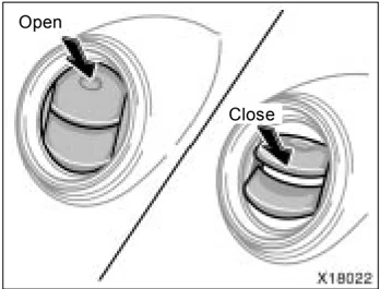
If air flow control is not satisfactory, check the side vents. The side vents may be opened or closed as shown.
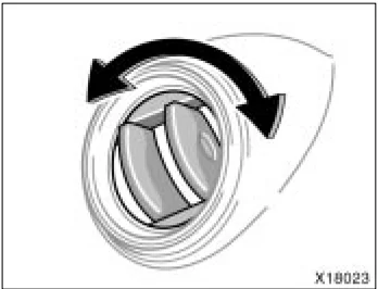
You can change air flow direction by turning the side vents.
Air conditioning filter—
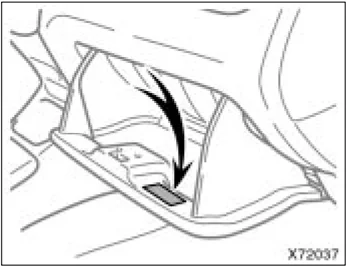
The air conditioning filter information label is placed inside of the glove box as shown and indicates that a filter has been installed.
The air conditioning filter prevents dust from entering the vehicle through the air conditioning vent.
174
—Checking and replacing the air conditioning filter
The air conditioning filter may clog after long use. The filter may need to be replaced if the air flow of the air conditioning and heater experiences extreme reductions in operating efficiency, or if the windows begin to fog up easily.
To maintain the air conditioning efficiency, inspect and replace the air conditioning filter according to the maintenance schedule. In dusty areas or areas with heavy traffic flow, such as inner city or desert areas, early replacement may be required. (For scheduled maintenance information, please refer to the “Scheduled Maintenance Guide” or “Owner’s Manual Supplement”. )
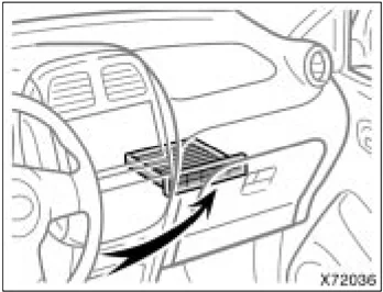
The air conditioning filter is behind the glove box.
- Push in each side of the glove box to disconnect the claws.
175
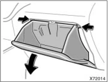
 X72015
- Remove the filter case from the filter outlet as shown in the illustration.
 X72025
- Remove the filter from the filter case.
- Inspect the filter on the surface. If it is dirty, it should be replaced.
INFORMATION
The air filter should be installed properly in position. The use of air conditioning with the air filter removed may cause deteriorated dustproof performance and then affect air conditioning performance.
176
SECTION 1- 10
OPERATION OF INSTRUMENTS AND CONTROLS
Other equipment
- Clock. . . . . . . . . . . . . . . . . . . . . . . . . . . . . . . . . . . . . . . . . . . . . . . . . . . . . . . . . . . . . . . . . . . . . . . . . . . . . . . . . . . . . . . . . . . . . . . . . . . . . . . . . . . . . . . . . . . . . . . . . . . . . . . . . . . . . . . . . . . . . . . . . . . . . . . . . . . . . . . . . . . . . . . . . . . . . . . . . . . . . . . . . . . . . . . . . . . . . . . . . . . . ........ 178
- Cigarette lighter and ashtrays . . . . . . . . . . . . . . . . . . . . . . . . . . . . . . . . . . . . . . . . . . . . . . . . . . . . . . . . . . . . . . . . . . . . . . . . . . . . . . . . . . . . . . . . . . . . . . . . . . . . . . . . . . . ........ 178
- Power outlets . . . . . . . . . . . . . . . . . . . . . . . . . . . . . . . . . . . . . . . . . . . . . . . . . . . . . . . . . . . . . . . . . . . . . . . . . . . . . . . . . . . . . . . . . . . . . . . . . . . . . . . . . . . . . . . . . . . . . ........

Clock
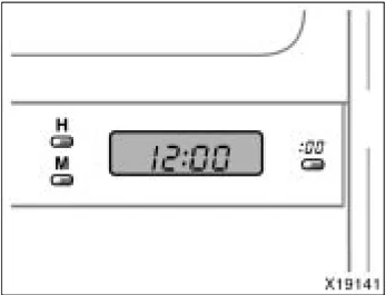
To reset the hour: Push the “H” button. To reset the minutes: Push the “M” button. If quick adjustment to a full hour is desired, push the “:00” button. For example, if the “:00” button is depressed when the time is between 1:01—1:29, the time will change to 1:00. If the time is between 1:30—1:59, the time will change to 2:00. The key must be in the “ACC” or “ON” position. If the electrical power source has been disconnected from the clock, the time display will automatically be set to 1:00 (one o’clock).
Cigarette lighter and ashtrays
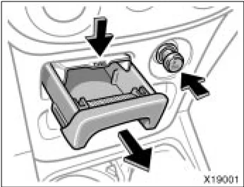
Cigarette lighter and front ashtray
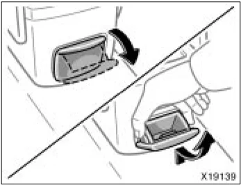
Rear ashtray
CIGARETTE LIGHTER To use the cigarette lighter, press it in. After it finishes heating up, it automatically pops out ready for use. If the engine is not running, the key must be in the “ACC” position. Do not hold the cigarette lighter pressed in. Use a Toyota genuine cigarette lighter or equivalent for replacement.
ASHTRAYS To use the ashtray, pull it out. When finished with your cigarette, thoroughly extinguish it in the ashtray to prevent other cigarette butts from catching fire. After using the ashtray, push it back in completely. Front: To remove the ashtray, press down on the lock spring plate and pull it out. Rear: To remove the ashtray, hold both sides of it and pull up slightly but firmly. Pull the bottom out of the holder.
178
CAUTION To reduce the chance of injury in case of an accident or sudden stop while driving, always completely close the ashtray after use.
Power outlets
 X19158
Front
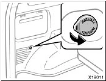
The power outlets are designed for power supply for car accessories. The key must be in the “ACC” or “ON” position for the power outlets to be used.
NOTICE ◆To prevent the fuse from being blown, do not use the electricity over the total vehicle capacity of 12V/120W (front and rear outlets together). ◆To prevent the battery from being discharged, do not use the power outlets longer than necessary when the engine is not running. ◆Close the power outlet lids when the power outlets are not in use. Inserting anything other than an appropriate plug that fits the outlet, or allowing any liquid to get into the outlet may cause electrical failure or short circuits.
 X19011
Rear
179
Glove box
 X19002
To use the glove box, do this. To open: Pull the lever. To lock: Insert the master key and turn it clockwise.
CAUTION To reduce the chance of injury in case of an accident or a sudden stop, always keep the glove box door closed while driving.
Garage door opener
 X19158
The garage door opener (HomeLink® Universal Transceiver) is manufactured under license from HomeLink® and can be programmed to operate garage doors, gates, entry doors, door locks, home lighting systems, and security systems, etc.
(a) Programming the HomeLink® The HomeLink® in your vehicle has 3 buttons and you can store one program for each button.
To ensure correct programming into the HomeLink®, install a new battery in the hand-held transmitter prior to programming.
The battery side of the hand-held transmitter must be pointed away from the HomeLink® during the programming process.
For Canadian users, follow the procedure in "Programming an entrance gate/Programming all devices in the Canadian market".
- Decide which of 3 HomeLink® buttons you want to program.
- Place your hand-held garage transmitter 25 to 75 mm (1 to 3 in.) away from the surface of the HomeLink®.
Keep the indicator light on the HomeLink® in view while programming.
180
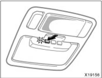
- Simultaneously press and hold the hand-held garage transmitter button along with the selected HomeLink® button.
- When the indicator light on the HomeLink® changes from a slow to a rapid flash after 20 seconds, you can release both buttons.
- Test the operation of the HomeLink® by pressing the newly programmed button. If programming a garage door opener, check to see if the garage door opens and closes.
If the garage door does not operate, identify if your garage transmitter is of the "Rolling Code" type. Press and hold the programmed HomeLink® button. The garage door has the rolling code feature if the indicator light (on the HomeLink®) flashes rapidly and then remains lit after 2 seconds. If your garage transmitter is the "Rolling Code" type, proceed to the heading "Programming a rolling code system". 6. Repeat steps 2 through 5 for each remaining HomeLink® button to program another device.
Programming a rolling code system If your device is "Rolling Code" equipped, it is necessary to follow steps 1 through 4 under the heading "Programming the HomeLink®" before proceeding with the steps listed below.
- Locate the "training" button on the ceiling mounted garage door opener motor. The exact location and color of the button may vary by brand of garage door opener. Refer to the owner's guide supplied by the garage door opener manufacturer for the location of this "training" button.
- Press the "training" button on the ceiling mounted garage door opener motor. Following this step, you have 30 seconds in which to initiate step 3 below.
- Press and release the vehicle's programmed HomeLink® button twice. The garage door may open. If the door does open, the programming process is complete. If the door does not open, press and release the button a third time. This third press and release will complete the programming process by opening the garage door.
The ceiling mounted garage door opener motor should now recognize the HomeLink® unit and be able activate the garage door up/down. 4. Repeat steps 1 through 3 for each remaining HomeLink® button to program another rolling code system.
Programming an entrance gate/programming all devices in the Canadian market
- Decide which of the 3 HomeLink® buttons you want to program.
- Place your hand-held gate/device transmitter 25 to 75 mm (1 to 3 in.) away from the surface of the HomeLink®.
Keep the indicator light on the HomeLink® in view while programming. 3. Press and hold the selected HomeLink® button. 4. Continuously press and release (cycle) the hand-held gate/device transmitter button every two seconds until step 5 is complete. 5. When the indicator light on the HomeLink® changes from a slow to a rapid flash after 20 seconds, you can release both buttons.
181
- Test the operation of the HomeLink® by pressing the newly programmed button. Check to see if the gate/device operates correctly.
- Repeat steps 1 through 6 for each remaining HomeLink® button to program another device.
Programming other devices To program other devices such as home security systems, home door locks or lighting, contact your authorized Toyota dealer for assistance.
Reprogramming a button Individual HomeLink® buttons cannot be erased, however, to reprogram a single button, follow the procedure “Programming the HomeLink®”.
(b) Operating the HomeLink® To operate the HomeLink®, press the appropriate HomeLink® button to activate the programmed device. The HomeLink® indicator light should come on. The HomeLink® continues to send the signal for up to 20 seconds as long as the button is pressed.
(c) Erasing the entire HomeLink® memory (all three programs) To erase all previously programmed codes at one time, press and hold down the 2 outside buttons for 20 seconds until the indicator light flashes.
If you sell your vehicle, be sure to erase the programs stored in the HomeLink® memory.
CAUTION
- When programming the HomeLink® Universal Transceiver, you may be operating a garage door or other device. Make sure people and objects are out of the way of the garage door or other device to prevent potential harm or damage.
- Do not use this HomeLink® Universal Transceiver with any garage door opener that lacks the safety stop and reverse feature as required by federal safety standards. (This includes any garage door opener model manufactured before April 1, 1982.) A garage door opener which cannot detect an object (signaling the door to stop and reverse), does not meet current federal safety standards. Using a garage door opener without these features increases risk of serious injury or death.
182
Garage door opener box
This device complies with Part 15 of the FCC Rules and with RSS-210 of the IC Rules. Operation is subject to the following two conditions: (1) This device may not cause harmful interference, and (2) this device must accept any interference that may be received, including interference that may cause undesired operation.
WARNING: This transmitter has been tested and complies with FCC and IC rules. Changes or modifications not expressly approved by the partly responsible for compliance could void the user’s authority to operate the device.
 X19093
The box is designed to store a garage door opener transmitter. Open the cover and remove the Velcro loop.
 X19094
Remove the paper strip covering the adhesive on back side of loop and adhere loop to back side of the transmitter near center.
183
 X19095
Please note if transmitter has wire clip for sun visor, this clip must be removed prior to adhesion of the Velcro.
 X19096
Place the transmitter with Velcro loop facing inside of box into the box. Make sure the transmitter button is located above button pins.
 X19097
Remove spacers from the center panel. Place the largest spacer on the pin that would be below transmitter button when the cover is closed. Close the cover.
184
X19090
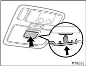
When the garage door opener transmitter is properly installed, you can operate the transmitter by pushing the center panel of the cover.
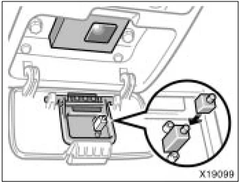
X19099
If the center panel does not contact your garage door opener transmitter: ● Check to see if spacer is on the correct pin. ● Attach another spacer to the top of original spacer. Check operation. If required, continue to add spacers until contact is achieved.
If the transmitter is clattering during driving, fill in a piece of felt or pad to prevent the transmitter from clattering.
CAUTION
● To reduce the chance of injury in case of an accident or a sudden stop, always keep the garage door opener box closed while driving.
● Keep the remaining spacers away from children.
185
Auxiliary boxes—
To use the auxiliary boxes, open as shown in the following illustrations.
Type C and D auxiliary boxes are equipped with a belt to hold the objects such as first-aid kit. See “—Using the holding belts” on page 187 for detailed information.
Type E auxiliary box is also designed to store the warning reflector.
The first-aid kit or warning reflector itself is not included as an original equipment.
CAUTION
To reduce the chance of injury in case of an accident or a sudden stop, always keep the auxiliary box closed while driving.
NOTICE
Type A: During hot weather, the interior of the vehicle becomes very hot. Do not leave anything flammable or deformable such as a lighter, glasses, etc. inside.
 X19132
Type A (front ceiling)
 X19085
Type C (left side of luggage compartment)
 X19013
Type B (instrument panel)
 X19059
Type D (right side of luggage compartment)
186
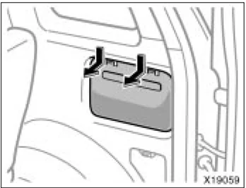
—Using the holding belts
 Type E (luggage compartment floor)
 Type C (left side of luggage compartment)
These auxiliary boxes are equipped with a belt to hold the objects. Type D auxiliary box—This belt is designed to hold the first-aid kit. To use the belt, do the following.
- To loosen: Pull the buckle forward.
- To tighten: Pull the belt. Make sure the objects are securely held.
 Type D (right side of luggage compartment)
187
Front cup holder
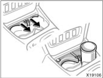
The cup holder is designed for holding cups or drink-cans securely. To use the holder, pull its end. The cup holder can be adjustable to the size of the cups or drink-cans by changing the arm position.
CAUTION
● Do not place anything else other than cups or drink-cans in the cup holder, as such items may be thrown about in the compartment and possibly injure people in the vehicle during sudden braking or in an accident. ● To reduce the chance of injury in case of an accident or sudden stop while driving, keep the cup holder closed when it is not in use.
Rear cup holder
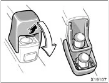
The cup holder is designed for holding cups or drink-cans securely. To use the holder, pull up the lever.
188
CAUTION
- Do not place anything else other than cups or drink-cans in the cup holder, as such items may be thrown about in the compartment and possibly injure people in the vehicle during sudden braking or in an accident.
- To reduce the chance of injury in case of an accident or sudden stop while driving, keep the cup holder closed when it is not in use.
To hold the cups or drink-cans securely, adjust the size of the cup holder in the following procedure.
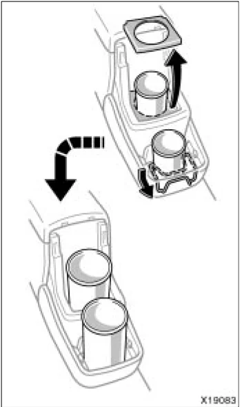
Upper side—To hold a bigger cup, remove the detachable adapter. Lower side—To hold a bigger cup, push down the spring.
189
Tie-down hooks
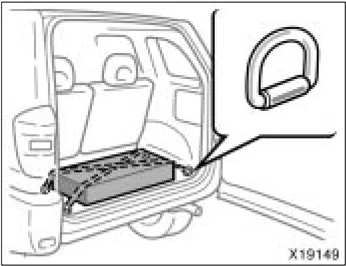
To secure your luggage, use the tie-down hooks as shown above.
See “—Stowage precautions” on page 221 in Section 2 for precautions when loading luggage.
CAUTION
To avoid personal injury, keep the tie-down hooks stored under the carpet when not in use.
NOTICE
Do not use the seat anchors instead of the tie-down hooks.
Grocery bag hooks (type A)
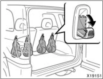
This hook is designed to hang things like grocery bags.
To use the hook, pull it down.
NOTICE
To prevent damage to the hook, do not hang any object heavier than 4 kg (8.8 lb.) on it.
Grocery bag hooks (type B)
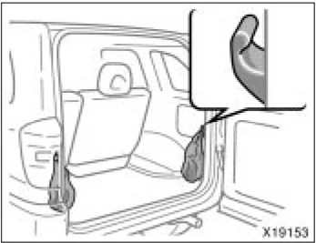
This hook is designed to hang things like grocery bags.
NOTICE
To prevent damage to the hook, do not hang any object heavier than 4 kg (8.8 lb.) on it.
190
Luggage cover
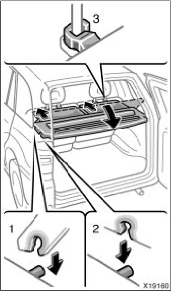
To use the luggage cover:
- Hook the front end of the luggage cover board onto the front protrusions.
- Lower the rear side of luggage cover board and hook onto the rear protrusions.
- Pull out the cloth portion of the cover and attach the front hooks to the head restraint.
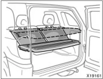
The luggage cover also can be set at the lower position.
CAUTION
● Do not place anything on the luggage cover. Such items may be thrown about and possibly injure people in the vehicle during sudden braking or a collision. ● To reduce the chance of injury in case of an accident or sudden stop, make sure the luggage cover is secured in place.
191
NOTICE Do not fold the seatback forward while the luggage cover is set.
If the luggage cover is left to be removed, place it somewhere other than the passenger compartment. This will prevent passengers from injury in the event of a sudden stop or an accident.
Separation net
(a) Behind the rear seats
(b) Behind the front seats* (tumbling the rear seats)
(c) Behind the front seats* (removing the rear seats)
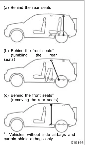
*: Vehicles without side airbags and curtain shield airbags only X1S146
You can separate the luggage compartment by installing the separation net as shown in the illustrations.
192
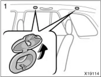
- Raise up the cover.
 2. Insert one side of the net stay into the net fixing hole. Press the stay to contract and insert the other side of the stay into the other fixing hole. Push the net forward.
 (a) Behind the rear seats
3. Hook the claw of the strap over the front tie down hook.
193
 (b) Behind the front seats
(tumbling the rear seats)
- Tumble the rear seat cushions and hook the claw of the strap over the rear hinge of the rear seat. (See “—Tumbling rear seats” on page 35 in Section 1-3.)
 (c) Behind the front seats
(removing the rear seats)
- Remove the rear seats and hook the claw of the strap over the front hinge of the rear seat as shown above. (See “—Removing rear seats” on page 38 in Section 1-3.)
 4. Pull the end of the belt to stretch the net securely.
Make sure the net does not interfere with a reclined seatback or head restraint.
CAUTION When not using the separation net, make sure that the cover of the fixing hook is closed. If the cover is open, it might cause the unexpected injury like hitting a head.
194
Roof luggage carrier
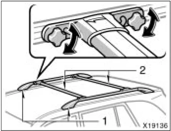
The roof luggage carrier consists of roof rails (1) attached to the roof and sliding cross rails (2).
To adjust the positions of cross rails, do this.
- Turn the knobs counterclockwise to loosen the cross rails.
- Slide the cross rails to the desired position for loading the luggages of various sizes.
- After adjusting, be sure to tighten the cross rails by turning knobs clockwise.
Follow the manufacture's instructions and precautions when installing the attachments or their equivalent.
CAUTION
When you load cargo on the roof luggage carrier, observe the following:
● Place the cargo so that its weight is distributed evenly between the front and rear axles.
● If loading long or wide cargo, never exceed the vehicle overall length or width. (See “Dimensions and weights” on page 312 in Section 8 for information on your vehicle overall length and width.)
● Before driving, make sure the cargo is securely fastened on the roof luggage carrier.
● Loading cargo on the roof luggage carrier will make the center of the vehicle gravity higher. Avoid high speeds, sudden starts, sharp turns, sudden braking or abrupt maneuvers, otherwise it may result in loss of control or vehicle rollover due to failure to operate this vehicle correctly.
● If driving for a long distance, on rough roads, or at high speeds, stop the vehicle now and then during the trip to make sure the cargo remains in its place.
● Do not exceed 34 kg (75 lb.) cargo weight on the roof luggage carrier.
NOTICE
When loading the luggages, be careful not to scratch the surface of the moon roof.
195
Floor mat
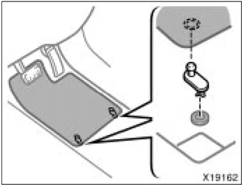
Use a floor mat of the correct size. If the floor carpet and floor mat have 2 holes, then they are designed for use with locking clips. Fix the floor mat with locking clips into the holes in the floor carpet.
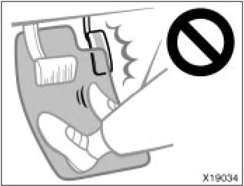
CAUTION Make sure the floor mat is properly placed on the floor carpet. If the floor mat slips and interferes with the movement of the pedals during driving, it may cause an accident.
196