Driver Controls
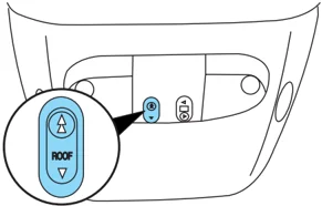
To open the moon roof: The moon roof is equipped with a one-touch open feature. Press and release the control. The moon roof will open to the “comfort” position. Press and release the control again to fully open. To stop the one-touch open feature press either the or control again.

To close the moon roof: Press and hold the control until the glass panel stops at the “comfort” position. Press and hold the control again until the glass stops moving. When fully closed, the rear portion of the glass panel will appear higher than the front portion.
To vent the moon roof: Press and hold the control. The moon roof must be in the closed position in order to move it into the vent position. To close, press and hold the control until the glass panel stops moving.
The moon roof has a built-in sliding shade that can be manually opened or closed when the glass panel is shut. To close the shade, pull it toward the front of the vehicle.
When closing the moon roof, you should verify that it is free of obstructions and ensure that children and/or pets are not in the proximity of the moon roof opening.
HOMELINK® WIRELESS CONTROL SYSTEM (IF EQUIPPED)
The HomeLink® Wireless Control System, located on the driver’s visor, provides a convenient way to replace up to three hand-held transmitters with a single built-in device. This feature will learn the radio frequency codes of most transmitters to operate garage doors, entry gate operators, security systems, entry door locks, and home or office lighting.
When programming your HomeLink® Wireless Control System to a garage door or gate, be sure that people and objects are out of the way to prevent potential harm or damage.
Do not use the HomeLink® Wireless Control System with any garage door opener that lacks safety stop and reverse features as required by
67
Driver Controls
U.S. federal safety standards (this includes any garage door opener model manufactured before April 1, 1982). A garage door which cannot detect an object, signaling the door to stop and reverse, does not meet current U.S. federal safety standards. For more information, contact HomeLink® at: www.homelink.com or 1-800-355-3515.
Retain the original transmitter for use in other vehicles as well as for future programming procedures (i.e. new HomeLink® equipped vehicle purchase). It is also suggested that upon the sale of the vehicle, the programmed Homelink® buttons be erased for security purposes, refer to Programming in this section.
Programming
Do not program HomeLink® with the vehicle parked in the garage.
Note: Your vehicle may require the ignition switch to be turned to the ACC position for programming and/or operation of the HomeLink®. It is also recommended that a new battery be placed in the hand-held transmitter of the device being programmed to HomeLink® for quicker training and accurate transmission of the radio-frequency signal.
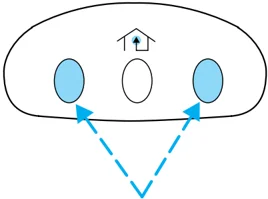
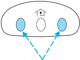
- Press and hold the two outside buttons releasing only when the indicator light begins to flash after 20 seconds. Do not repeat step one to program additional hand-held transmitters to the remaining two HomeLink® buttons. This will erase previously programmed hand-held transmitter signals into HomeLink®.
-
Position the end of your hand-held transmitter 1–3 inches (2–8 cm) away from the HomeLink® button you wish to program (located on your visor) while keeping the indicator light in view.
-
Simultaneously press and hold both the HomeLink® and hand-held transmitter button. Do not release the buttons until step 4 has been completed.
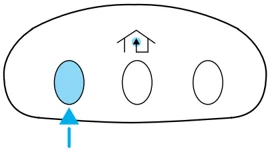
Some entry gates and garage door openers may require you to replace step 3 with procedures noted in the “Gate Operator and Canadian Programming” in this section for Canadian residents.
68
Driver Controls
- The indicator light will flash slowly and then rapidly. Release both buttons when the indicator light flashes rapidly. (The rapid flashing light indicates acceptance of the hand-held transmitters’ radio frequency signals.)
- Press and hold the just-trained HomeLink® button and observe the indicator light. If the light is constant, programming is complete and your device should activate when the HomeLink® button is pressed and released. Note: To program the remaining two HomeLink® buttons, begin with step 2 in the “Programming” section — do not repeat step 1. Note: If the indicator light blinks rapidly for two seconds and then turns to a continuous red, proceed with steps 6 through 8 to complete programming of a rolling code equipped device.
- At the garage door opener receiver (motor-head unit) in the garage, locate the “learn” or “smart” button (usually near where the hanging antenna wire is attached to the unit).
- Press and release the “learn” or “smart” button. (The name and color of the button may vary by manufacturer.) Note: There are 30 seconds in which to initiate step eight.
- Return to the vehicle and firmly press, hold for two seconds and release the HomeLink® button. Repeat the press/hold/release sequence again, and, depending on the brand of the garage door opener (or other rolling code equipped device), repeat this sequence a third time to complete the programming.
HomeLink® should now activate your rolling code equipped device. To program additional HomeLink® buttons begin with step 2 in the “Programming” section. For questions or comments, please contact HomeLink at www.homelink.com or 1-800-355-3515.
Gate Operator & Canadian Programming
During programming, your hand-held transmitter may automatically stop transmitting — not allowing enough time for HomeLink® to accept the signal from the hand-held transmitter.
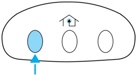
After completing steps 1 and 2 outlined in the “Programming” section, replace step 3 with the following:
Note: If programming a garage door opener or gate operator, it is advised to unplug the device during the “cycling” process to prevent overheating.
69
Driver Controls
- Continue to press and hold the HomeLink® button (note step 3 in the “Programming” section) while you press and release — every two seconds (“cycle”) your hand-held transmitter until the frequency signal has been accepted by the HomeLink®. The indicator light will flash slowly and then rapidly after HomeLink® accepts the radio frequency signal.
- Proceed with step 4 in the “Programming” section.
Operating the HomeLink® Wireless Control System
To operate, simply press and release the appropriate HomeLink® button. Activation will now occur for the trained product (garage door, gate operator, security system, entry door lock, or home or office lighting etc.). For convenience, the hand-held transmitter of the device may also be used at any time. In the event that there are still programming difficulties, contact HomeLink® at www.homelink.com or 1-800-355-3515.
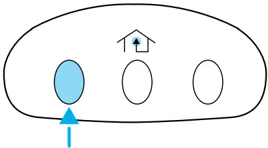
Erasing HomeLink® buttons
To erase the three programmed buttons (individual buttons cannot be erased):
- Press and hold the two outer HomeLink® buttons until the indicator light begins to flash-after 20 seconds. Release both buttons. Do not hold for longer that 30 seconds.
HomeLink® is now in the train (or learning) mode and can be programmed at any time beginning with step 2 in the “Programming” section.
Reprogramming a single HomeLink® button
To program a device to HomeLink® using a HomeLink® button previously trained, follow these steps:
- Press and hold the desired HomeLink® button. Do NOT release the button.
70
Driver Controls
- The indicator light will begin to flash after 20 seconds. Without releasing the HomeLink® button, follow step 2 in the “Programming” section.
For questions or comments, contact HomeLink® at www.homelink.com or 1-800-355-3515.
MESSAGE CENTER (IF EQUIPPED)
With the ignition in the ON position, the message center, located on your instrument cluster, displays important vehicle information through a constant monitor of vehicle systems. You may select display features on the message center for a display of status preceded by a brief indicator chime. The system will also notify you of potential vehicle problems with a display of system warnings followed by a long indicator chime.
Selectable features
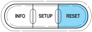
Reset
Press this control to select and reset functions shown in the INFO menu and SETUP menu.
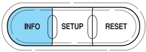
Info menu
This control displays the following control displays:
- Odometer/Compass
- Trip odometer/Odometer/Compass
- Distance to Empty
- Average Fuel Economy
- Trip Elapsed Drive Time
Odometer/Trip odometer
Refer to Gauges in the Instrument Cluster chapter.
71
Driver Controls
Compass display
The compass reading may be affected when you drive near large buildings, bridges, power lines and powerful broadcast antenna. Magnetic or metallic objects placed in, on or near the vehicle may also affect compass accuracy.
Usually, when something affects the compass readings, the compass will correct itself after a few days of operating your vehicle in normal conditions. If the compass still appears to be inaccurate, a manual calibration may be necessary. Refer to Compass zone/calibration adjustment.
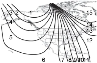
Most geographic areas (zones) have a magnetic north compass point that varies slightly from the northerly direction on maps. This variation is four degrees between adjacent zones and will become noticeable as the vehicle crosses multiple zones. A correct zone setting will eliminate this error. Refer to Compass zone/calibration adjustment.
Compass zone/calibration adjustment
- Determine your magnetic zone by referring to the zone map.
- Turn ignition to the ON position.
- Start the engine.
- From Info menu, select the Compass/Odometer function. (Do not select Trip, DTE, or AFE. The top of the message center must be blank).
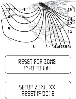
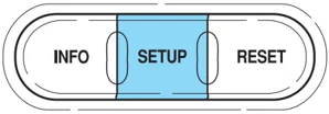
- Press and hold the SETUP and RESET controls until the message center display changes to show the current zone setting (XX).
RESET FOR ZONE INFO TO EXIT
- Press the SETUP control repeatedly until the correct zone setting for your geographic location is displayed on the message center. The range of zone values are from 01 to 15 and “wraps” back to 01.
SETUP ZONE XX RESET IF DONE
72
Driver Controls
- To exit the zone setting mode, and to “lock in” your change, press and release the RESET control.
Perform compass calibration in an open area free from steel structures and high voltage lines. For optimum calibration, turn off all electrical accessories (heater/air conditioning, wipers, etc.) and make sure all vehicle doors are shut.
-
Press the RESET control to start the compass calibration function.
-
Slowly drive the vehicle in a circle (less than 3 mph [5 km/h]) until the CIRCLE SLOWLY TO CALIBRATE display changes to CALIBRATION COMPLETED. It will take up to five circles to complete calibration.
-
The compass is now calibrated.
Distance to empty (DTE)
Selecting this function from the INFO menu estimates approximately how far you can drive with the fuel remaining in your tank under normal driving conditions.
Remember to turn the ignition OFF when refueling to allow this feature to correctly detect the added fuel.
The DTE function will display LOW FUEL LEVEL and sound a tone for one second when you have approximately 50 miles (80 km) to empty. If you RESET this warning message, this display and tone will return within 10 minutes.
DTE is calculated using a running average fuel economy, which is based on your recent driving history of 500 miles (800 km). This value is not the same as the average fuel economy display. The running average fuel economy is reinitialized to a factory default value if the battery is disconnected.
73
Driver Controls
Average fuel economy (AFE)
Select this function from the INFO menu to display your average fuel economy in miles/gallon or liters/100 km.
If you calculate your average fuel economy by dividing gallons of fuel used by 100 miles traveled (kilometers traveled by liters used), your figure may be different than displayed for the following reasons:
- Your vehicle was not perfectly level during fill-up
- Differences in the automatic shut-off points on the fuel pumps at service stations
- Variations in top-off procedure from one fill-up to another
- Rounding of the displayed values to the nearest 0.1 gallon (liter)
- Drive the vehicle at least 8 km (5 miles) with the speed control system engaged to display a stabilized average.
- Record the highway fuel economy for future reference.
It is important to press the RESET control after setting the speed control to get accurate highway fuel economy readings.
Trip elapsed drive time
Select this function from the INFO menu to display a timer.
To operate the Trip Elapsed Drive Time perform the following:
- Press and release RESET in order to start the timer.
- Press and release RESET to pause the timer.
- Press and hold RESET for 2 seconds in order to reset the timer.
74
Driver Controls
Setup menu
Press this control for the following displays:
• System Check
• Units (English/Metric)
• Autolock
• Autolamp Delay
• Language
System check
Selecting this function from the SETUP menu causes the message center to cycle through each of the systems being monitored. For each of the monitored systems, the message center will indicate either an OK message or a warning message for three seconds.
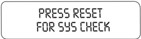
Pressing the RESET control cycles the message center through each of the systems being monitored.
The sequence of the system check report and how it appears in the message center is as follows:
- FUEL LEVEL
- ENGINE TEMP
- OIL PRESSURE
- BRAKE FLUID LEVEL
- CHARGING SYSTEM
Units (English/Metric)
-
Select this function from the SETUP menu for the current units to be displayed.
-
Press the RESET control to change from English to Metric.
Autolocks
This feature automatically locks all vehicle doors when the vehicle is shifted into any gear, putting the vehicle in motion.
75
Driver Controls
- To disable/enable the autolock feature, select this function from the SETUP control for the current display mode.
- Press the RESET control to turn the autolocks ON or OFF.
Autolamp delay
This feature keeps your headlights on for up to three minutes after the ignition is switched off.
-
To disable/enable the autolamp delay feature, select this function from the SETUP control for the current display mode.
-
Press the RESET control to turn the autolamp delay ON or OFF.
Language
-
Select this function from the SETUP menu for the current language to be displayed.
-
Pressing the RESET control cycles the message center through each of the language choices.
-
Press and hold the RESET control to set the language choice.
System warnings
System warnings alert you to possible problems or malfunctions in your vehicle's operating systems.
76
Driver Controls
In the event of a multiple warning situation, the message center will cycle the display to show all warnings by displaying each one for 4 seconds.
The message center will display the last selected feature if there are no more warning messages. This allows you to use the full functionality of the message center after you acknowledge the warning by pressing the RESET control and clearing the warning message.
Warning messages that have been reset are divided into two categories:
- They will reappear on the display ten minutes from the reset.
- They will not reappear until an ignition OFF-ON cycle has been completed.
This acts as a reminder that these warning conditions still exist within the vehicle.
DOOR AJAR. Displayed when a door is not completely closed.
CHECK ENGINE TEMPERATURE. Displayed when the engine coolant is overheating. Stop the vehicle as soon as safely possible, turn off the engine and let it cool. Check the coolant and coolant level. Refer to Engine coolant in the Maintenance and Specifications chapter. If the warning stays on or continues to come on, contact your dealer as soon as possible.
REDUCED ENGINE POWER. Displayed when the engine is overheating. Stop the vehicle as soon as safely possible, turn off the engine. If the warning stays on or continues to come on, contact your dealer as soon as possible.
Driver Controls
STOP ENGINE SAFELY. Displayed when the engine is overheating. Stop the vehicle as soon as safely possible, turn off the engine. If the warning stays on or continues to come on, contact your dealer as soon as possible.
LOW FUEL LEVEL. Displayed as an early reminder of a low fuel condition.
CHECK CHARGING SYSTEM. Displayed when the electrical system is not maintaining proper voltage. If you are operating electrical accessories when the engine is idling at a low speed, turn off as many of the electrical loads as soon as possible. If the warning stays on or comes on when the engine is operating at normal speeds, have the electrical system checked as soon as possible.
LOW BRAKE FLUID LEVEL. Indicates the brake fluid level is low and the brake system should be inspected immediately. Refer to Checking and adding brake fluid in the Maintenance and Specifications chapter.
LOW OIL PRESSURE. Displayed when the engine oil pressure is low. If this warning message is displayed, check the level of the engine oil. Refer to Engine oil in the Maintenance and Specifications chapter for information about adding engine oil. If the oil level is OK and this warning persists, shut down the engine immediately and contact your dealership for service.
CHECK FUEL CAP. Displayed when the fuel filler cap is not properly installed. Check the fuel filler cap for proper installation. Refer to Fuel filler cap under the Fuel Information section in the Maintenance and Specifications chapter.
ENGINE FAILSAFE MODE. Displayed when the engine has defaulted to a 'limp-home' operation. If the warning stays on or continues to come on, contact your dealer as soon as possible.
DATA ERR. These messages indicate improper operation of the vehicle network communication between electronic modules.
• Fuel computer
• Charging system
• Autolamp delay
• Auto locks
• Brake fluid
• Compass
• Outside temperature
• Engine sensor
78
Driver Controls
Contact your dealer as soon as possible if these messages occur on a regular basis.
MINI MESSAGE CENTER ELECTRONIC COMPASS/TEMPERATURE DISPLAY (IF EQUIPPED)
Outside air temperature
The outside temperature display is contained in the instrument cluster and displays all the time, except when a warning message is present.
To turn the display off or change the display from English to metric see your dealer.
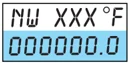
Compass
The compass reading may be affected when you drive near large buildings, bridges, power lines and powerful broadcast antennas. Magnetic or metallic objects placed in, on or near the vehicle may also affect compass accuracy.
Usually, when something affects the compass readings, the compass will correct itself after a few days of operating your vehicle in normal conditions. If the compass still appears to be inaccurate, a manual calibration may be necessary. Refer to Compass calibration adjustment.
Most geographic areas (zones) have a magnetic north compass point that varies slightly from the northerly direction on maps. This variation is four degrees between adjacent zones and will become noticeable as the vehicle crosses multiple zones. A correct zone setting will eliminate this error. Refer to Compass zone adjustment.
Compass zone adjustment
79
Driver Controls
- Determine which magnetic zone you are in for your geographic location by referring to the zone map.
- Turn ignition to the ON position.
- Start the engine.
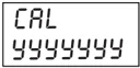
- Press the ODO reset button in the cluster, hold for six seconds and release. You will see that ZONE appears in the instrument cluster display.
ZONE XX yyyyyyy
- Press and release the button until the desired zone number appears. Note: The range of zone values are from 01 to 15 and "wraps" back to 01.
- When you get to the desired ZONE number, hold the button down to "lock in" the new value.
The cluster display will return to the "normal" mode when the button has not been pressed for 6 seconds.
Compass calibration adjustment
Perform this adjustment in an open area free from steel structures and high voltage lines. For optimum calibration, turn off all electrical accessories (heater/air conditioning, wipers, etc.) and make sure all vehicle doors are shut.
- Start the vehicle.
- To enter the compass calibration mode, press and hold the button for greater than eight seconds. The display will then show CAL in the display window.
CAL yyyyyyy
- Drive the vehicle slowly (less than 3 mph [5 km/h]) in circles until CAL indicator turns off. As many as 5 complete circles may be required.
- The compass is now calibrated.
80
Driver Controls
TAILGATE LOCK (IF EQUIPPED)
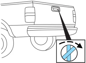
Your vehicle may be equipped with a tailgate lock designed to prevent theft of the tailgate.
- Insert ignition key and turn to the right to engage lock.
- Turn ignition key to the left to unlock.
TAILGATE REMOVAL
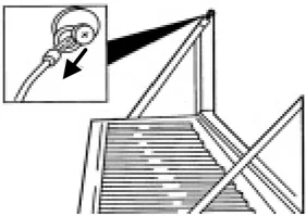
Your tailgate is removable to allow more room for loading.
- Lower the tailgate.
- Use a screwdriver to pry the spring clip (on each connector) past the head of the support screw. Disconnect cable.
- Disconnect the other cable.
- Lift tailgate to a 45 degree angle from horizontal.
- Lift right side off of its hinge.
- Lift tailgate to a 80 degree angle from horizontal.
- Remove tailgate from left side hinge by sliding tailgate to the right.
To install, follow the removal procedures in reverse order.
81
Driver Controls
BED EXTENDER (IF EQUIPPED)
Your vehicle may be equipped with a bed extender designed to extend the pickup box for longer loads.
To extend the bed extender:
- Lower tailgate.
- Pull the round knobs on each side of the extender to release it from the pickup box.
- Pivot extender on to the tailgate.
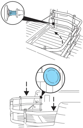
- Evenly push down on the extender and push the round knobs in on each side locking it in place.
Green markings on the shaft indicate the locked position. The locking clip screws below the middle bar can be tightened counterclockwise for extra security.
Note: If the red marking on the shaft is visible, the bed extender is not locked or properly secured.
To stow the bed extender, follow steps one through four in reverse order.
The bed extender may be used to secure a load of up to 46 kg (100 lbs.) on the tailgate.
The bed extender should always be kept in the stowed position with the tailgate closed when not in use.
When driving the vehicle off road, the bed extender should be removed and the tailgate closed.
82
Driver Controls
To remove the bed extender:
- Extend the bed extender.
- Pull the round knobs on each side of the extender to unlock it.
Make sure the locking clip screws are loose before removing the extender.
- Press the locking clips below the middle bar on each side and lift the extender out of the bed.
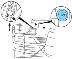
Note: Remove and store the bed extender when not in use.
To install the bed extender, follow the removal procedure in reverse order.
83